LED to Temp idiot light

Includes wiring and battery, generating system, starting system,
ignition system, windscreen wipers, lighting system and instruments and gauges.

Moderators: reidy, Blacky

rosco
Posts: 2569
Joined: Wed Feb 04, 2004 8:34 pm
State: VIC
Location: Melbourne

LED to Temp idiot light

Post by rosco »

Hi everyone,

this is an article I wrote for someone whilst dormant - thought someone may be interested

Warning! it's long..............

Part 1

sorry - haven't been able to place pix mentioned as yet, just dumb I guess.......


Finally got around to finding some pix as requested to show how the alarm LED (light emitting diode) was fitted to my Temp idiot light.

I disassembled the unit and placed the components out in order (pic gauge 002).
Image
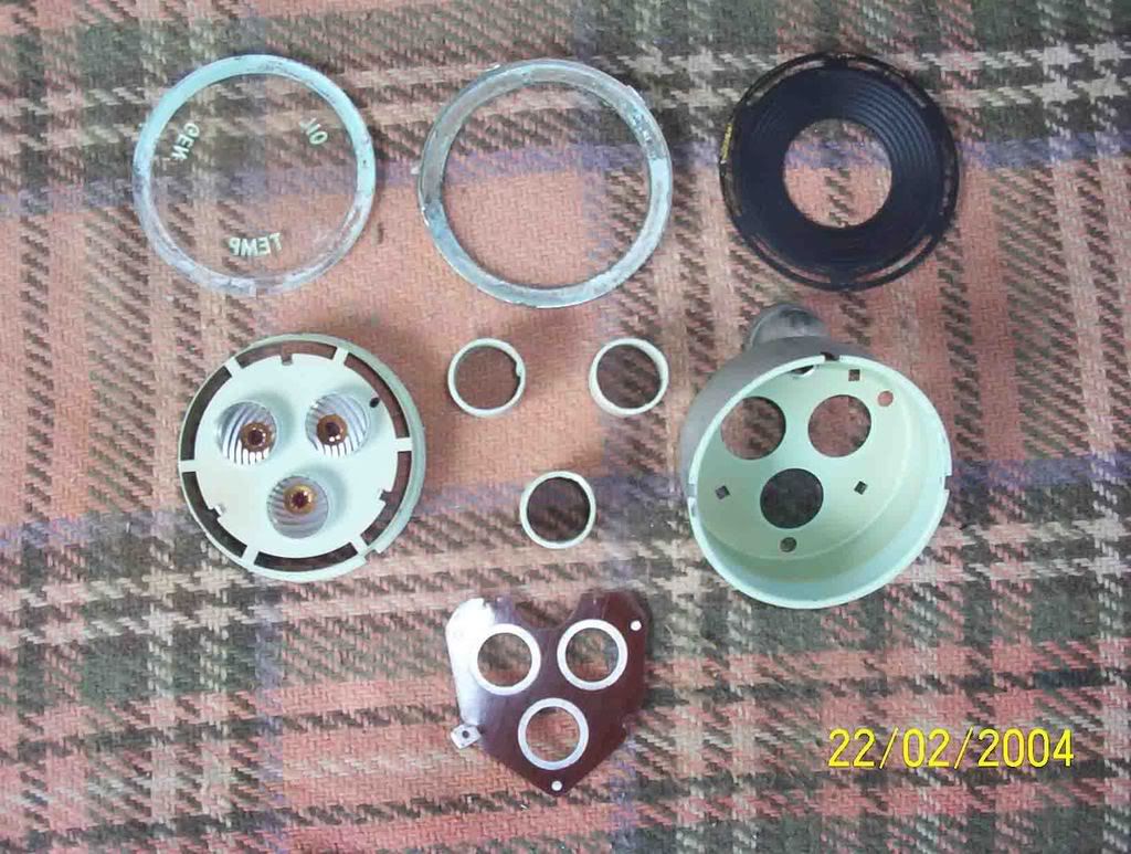
Originally I had intended to simply remove the jewel lens and replace it with a 5mm LED. You will see that realistically this would have looked totally different from the jewels (pic - gauge 005).
Image
I was going to file the hexagonal shape to the LED and try to “hide” it by darkening the red.
I don’t know if you have removed these jewels from your gauge yet, but to remove them you must (very) carefully prise the tangs from the jewel retainer then withdraw it from the face.

When I fitted the alarm I disassembled the supplied alarm indicator light and found it to be comprised an internal 3.5mm clear LED which illuminated red when operating.
The next thought was to somehow fit that small LED into the existing jewel.

I filed down the LED to its bare minimum (you can carefully file away the plastic coating down to a bare minimum providing sufficient covering is left over the anode/cathode) final size was 2.5 mm.
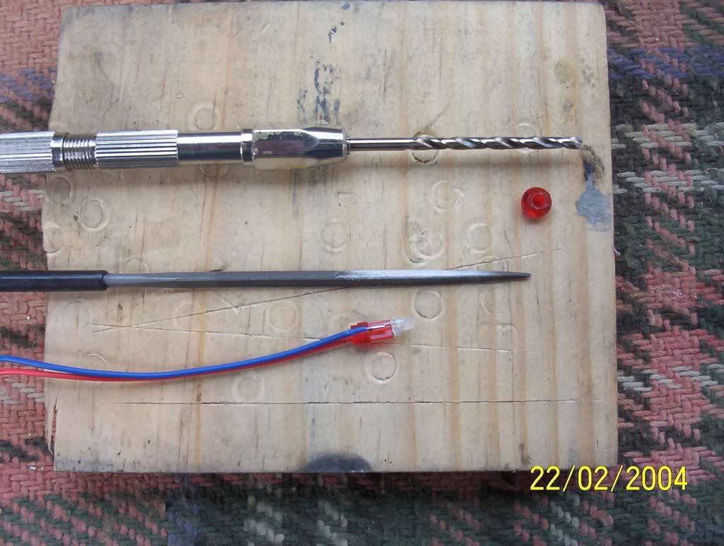
After measuring the remainder, it was found that there was sufficient “meat” in the jewel to permit drilling out so that an interference fit could be obtained (pic – gauge 007). Final drilled hole in rear of jewel was 3 mm. I used a “pin vise” to work the hole out to 3mm. Started with an 0.5 mm then worked through 0.8, 1.0, 1.5, 2.0, 2.5, 2.75 and 3.0 mm drills until the LED “just” fitted into the hole.
Image
Here is an excerpt from my log book………….

22/2/04 Disassembled tell tale gauge unit. Removed temperature light jewel and
drilled out from rear to 3 mm dia. Dismantled alarm LED filed led to 2.5 mm,
cut lens and re-fitted to jewel. re-fitted jewel, filed light shades down approx
2.5 mm and re-assembled gauge – araldite 5 min. to light shades.
Fitted rubber retainer to temperature shade tube.
Re-assembled and tested unit bare with 560 ohm resistor.


Once the LED was secured into the rear of the gauge (pic – gauge 009).
Image
It was re-assembled and tested. It has worked perfectly ever since – (pic gauge 010).
If you wish to run any LED (either a 3.5 mm or 5 mm) and use the 12v supply from your battery, a 560 ohm resistor (shown in pic gauge 005 – the small blue striped component) will break down the voltage to the required approx 2.2 volts (plus or minus depending on alternator output – they can tolerate a reasonable amount of variation) LED’s are very cheap but being a diode will only “work” one way – that is if it doesn’t work – connect the wires the other way around. It doesn’t matter which lead you fit the resistor to – it is not polarized…………..

You asked me of the Temperature gauge I have fitted…………… It is a VDO electronic unit. I had a set of “Arrow” gauges fitted to this car not long after purchasing it in 1972 but always disliked the temperature and oil pressure lines associated with them. I decided when doing the under-dash re-wiring back in 2001 to upgrade to electronic.

Here is the excerpt from my log book……………

05 Jan 02 VDO electric temperature gauge 310-010-014 – Burson’s 36.64
temperature gauge sender unit 320-002 – Burson’s 10.88


Part 2


I received a reply which stated confusion as to the purpose of fitting an LED to the Temperature light - wrote the following to expand .......


Hope I didn’t confuse everyone with the purpose of the fitting of that LED to the TEMP jewel – here’s the explanation.............

I forwarded a copy of my reply to the group as to the fitting of an LED to the TEMP jewel of my gauges because I considered someone else may want to do this - one day out there in the 22nd century.

It is a lot of trouble to go to, but I took up the challenge and in this case was successful – something to do with having too much time alone to ponder such things........

I don’t know if you are aware of the anti-theft stuff fitted to the car, but I decided to fit the LED of the burglar/anti-theft units to the non-used TEMP position of the gauge unit – that’s where the whole story is related to. I wouldn’t fit LED’s to the other two as there is little point (however, retirement is coming –might be a nice way to “fulfill” a couple of days).

I suppose I could have just fitted some sort of 12v output device to have the original globe give the various indications but wanted to have a little “play” with fitting an LED into the jewel.

I had heard of a 5 mm LED being fitted in lieu of the jewel but as you probably saw in one of the pix, they are very easily identified.

I am very hesitant to drill any more holes in my dash – there have been many over the years and the remnants of the little blighters are evident all over it – will finally get rid of those when I pull out and replace the front window – another “little” project I will get to along with all the associated tributary “projects” I have marked when that time comes.

I may somewhere down the track re-fit a temp warning feature, but this will also utilise the LED now fitted in the gauge – cannot for one moment foresee the two separate functions operating simultaneously.

I have not for many, many years used that jewel, instead disciplined myself to scan the auxiliary gauges frequently. Unless something goes amiss very quickly, it has been my experience that engine coolant temperature has the habit of increasing when the engine has greater demands placed upon it – usually by some initiation of the right foot.

Fortunately, I have not suffered a thermostat malfunction or hose failure thus far – I’m sure the “further to” project of combining idiot light and alarm unit LED will shortly follow should this occur.
It would probably take more than the interval between scans for the temperature to rise high enough to risk damage but...............

I know of one particular case where the owner had an audible alarm fitted to his oil and temp units – seems he just didn’t pay any attention to visual indicators ........ one engine and some considerable coupons later has educated his appreciation of them ................. I am also of the knowledge that he has reduced the frequency of purchasing tickets to the Police Ball and also running out of fuel!
I can already hear the next issue............ didn’t see the vehicle in front, was watching the gauges – guess the complicated demands of driving a vehicle is just too complex for some people?

Hope that clarifies some of the LED purpose?


To those who read this - you were warned, it was long.

frats,
Rosco
Last edited by rosco on Sun Dec 23, 2007 10:06 pm, edited 3 times in total.
mrs ratbox

Post by mrs ratbox »

do you have any ideas to replacing the illuminating globes with LED's, it's sort of been talked about else where and i've seen some on ebay that look pretty trik
rosco
Posts: 2569
Joined: Wed Feb 04, 2004 8:34 pm
State: VIC
Location: Melbourne

LED's

Post by rosco »

Hi Ratbox,

I'm sorry I am probably not going to be much use to you here but I have some thoughts on what you may have in mind............

The only way I have seen our incandescent globes replaced by LED's is by either fitting a 5 mm LED with an LED holder on the back of the panel or by the method I described above. There may be some other way but I do not have any knowledge of it.

Just fitting the 5mm would be a lot easier but you will still need to drop the voltage down to around 2.2 volts or you will blow them up - I don't remember at what voltage I blew my last one, but I think they are probably fairly safe up to about 3 - 3.5v for a short time.

Only one of the two leads of the LED will be positive they must be correctly connected or they will not work - you won't damage the LED if you wire it up back the front, it just won't work. That's what diodes do - let positive flow one way and negative the other........ sorry, OTT........

I can't remember whether the longer lead of the LED was positive or negative but they are always supplied with one lead longer.
In electronic terms one is the anode, the other the cathode.
I can look it up if you want, I'm just about off to bed now and was checking the mail.

As mentioned you will need to drop the 12 volt supply down to just over 2 volts or you'll blow the LED. I believe a 560 K ohm resistor is the one to use to do this. It doesn't matter which of the LED leads you connect the resistor to, it will drop the voltage either way.

The only other LED I have fitted was to another vehicle.
It was a very large flashing one of around 10 - 12 mm to indicate an immobiliser - that one had a built in resistor and just needed the correct polarity to make it work. We fitted the positive directly to a "always on" supoly at the fuse panel (cigarette lighter from memory) and the earth went to a toggle switch.
To get the LED to flash, the toggle switch was turned "on" and this made the connection to earth and completed the circuit.
LED's can flash almost indefinitely without noticeable drain on your battery - in fact I think you would be aware that super bright white LED's are now being sold in flash lamps quote a battery life of days........... can't imagine a great 12V multi amp battery ever suffering long term from a number of flashing LED's - can you?

Another plus for LED's is their life expectancy.
It was a shock to me to learn that often crash analysts can tell if you were braking at the point of impact just by the condition of the filaments in incandescent globes.............at it again, aren't I?

All these parts can be supplied by you local electronics store - they are really dirt cheap. Obviously marketed kits are more expensive but for convenience and the grab bag effect probably justified.

I suppose if you want to make a feature of it, you could drill and fit multiple LED's of different colours to function either individually or in combination - this is where your creativity can be unleashed.

As to getting them to work, in a sequence or such, you would probably need to construct a small circuit board to do the switching. This would be achieved by designing a circuit with an IC (Integrated Circuit or chip) - probably a 555 timer clock. or similar............ getting well beyond your original question now................

There are probably many on this site who understand electronics design much better than I and I would encourage them to come forward and suggest such an easy project- possibly using what is known as breadboard for the circuit to join components together on ........

Again, if you have dabbled a bit with electronics, drop in to you local store and see what kits they have........ you'll probably come out with at least one to try............

I have seen LPG fuel indicators operating using a bank of LED's to indicate the level............ the world of incandescent globes is fast coming to a timely end.

I know we love our old buses because of their antiquated componentry. For some the fitting of gadgets and fandangled wizardry is appealing, Suppose it's up to you what you want to install and achieve ............


Mail me if you want more - I'm sure there are many alternative uses to indicate this and that. It starts to get a bit silly when something lights up or flashes and you can't remember what it is indicating.......... we old timers get that with only a few different lights - maybe that's why there were only three in the idiot light panel................

Was that in the directton of what you were asking?

sorry folk,
been back five minutes and broken all my new rules already,

frats,
Rosco
User avatar
Devilrod
Posts: 7394
Joined: Fri Apr 30, 2004 12:55 pm
State: VIC
Location: Beaconsfield, Vic

Post by Devilrod »

Don't apologize, this info helps especially if you know nothing about LED's....
Speed and Style........... One day I'll get the speed bit.
mrs ratbox

Post by mrs ratbox »

picked up a basic idea of what you were saying
basically shouldn't be hard just have to make something to hold the LED and drop the voltage
as there are i think 4 globes in total 2 in speedo and 1 each fuel and idiot lights do you know if i would have to drop the voltage on each or drop the voltage then run them in a chain type configuration like christmas lights
karsten
Posts: 613
Joined: Wed Oct 17, 2007 6:31 am
State: NOT ENTERED
Location: bungendore nsw

leds

Post by karsten »

as a truck owner operator i am the owner of heaps of led,s and in the old festoon bulbs if you pulled up through the night and left your park lights on ie,roof and trailer lights glowing and there is quite a few the big girl would be dead buy morning , then came leds and us truckies happily converted to them as blow bulbs are a pain and where a liability issue should some moron run up you ass ,cause your blinker dont work, but with leds you can leave the lights on all night and there is no loss of power they are also far more reliable never had one fail i know there are leds available at hiway truck accessories in brisbane that fit strait in where old style bulbs went without modsthe are an led replacement bulb
when they start building them like that again i will buy a new car of them
rosco
Posts: 2569
Joined: Wed Feb 04, 2004 8:34 pm
State: VIC
Location: Melbourne

I got it wrong - sorry

Post by rosco »

Hi Ratbox,

I do a lot of writing but it seems my reading skills lack somewhat.......

Just got the drift of your original question -sorry, bit slow.

You are referring to the globes which actually show up the background of our instrument clusters.......... now I get it.

Umm............. yeah, ok - just having a think.

I don't know how others feel about this but I am having a bit of an issue here.

LED's work fine at a constant brightness - the more illumination you want, either the brighter type of LED or number of them will be required.

Something is nagging me with relation to our signals at work that it is not possible to be able to control the brightness of LED's at a controllable rate.
ie - they are on or off. We have had many trials and the result is that there are now three times as many during daylight than at night to display the various indications. We nearly had to put sunglasses on at night when apporaching them - I think there were even complaints from residents at some locations.

The incandescent globes used in our vehicle instrument clusters are positioned fairly exact to backlight the dials etc. You will notice if one globe is just out of it's holder the result is quite dull. With respect to LED's in this application, they would probably need to be placed immediately behind the reference dial and probably use some form of diffuser to spread their light evenly. I will give this some thought whilst at work - should be able to come up with something..............

I am not suggesting it would not be possible, and quite probably is - I can't recall an application of it that's all.

If you want to try this, and I will be extremely interested if you decide to do so, I will offer whatever advice I can if you get stuck, please keep me up to speed with where you are and what you have found/done.

I expect modern vehicles use LED's now but from what I have seen, they are in fact the instrument not the backlighting...........

Sorry for going off on a tangent yesterday, just got locked in on a "moon beam" again I'm afraid.

frats,
Rosco
Last edited by rosco on Sat Dec 01, 2007 9:11 am, edited 1 time in total.
rosco
Posts: 2569
Joined: Wed Feb 04, 2004 8:34 pm
State: VIC
Location: Melbourne

truck LED's

Post by rosco »

Great stuff Karsten,

this is what we need some lateral thinking.
Have seen them on trucks and caravans etc.....
I would expect they are rated for 12 volts..........and have inbuilt resistor to drop the voltage. Of course you could daisy chain them and drop it that way (like christmas tree lights ) but this would make them subject to failure if either one blows or a connection fails.

Thanks heaps Karsten, may be something to consider fitting additionally within our tail-lights, indicators in addition to the existing globes behind the covers for modified vehicles.

I think there may be issues if they were used to replace the bulb and still use the cover........... have to have a look at one working in bright sunlight.

frats,
Rosco
karsten
Posts: 613
Joined: Wed Oct 17, 2007 6:31 am
State: NOT ENTERED
Location: bungendore nsw

led

Post by karsten »

im not sure if this means anythink but if you have a 12 volt primemover and hook it to a trailer with leds they light up awsomely but if you then back a primeover that runs a 24 volt system up to that trailer it lights up the same no different and there is no volt reducer on the trailer have wired the trailer myself , and they are advertized from 6 to 36 volts just hook em up ,they where invented buy some fella in aus for trucks that suffer for many years with dull marker and tail light to increase night visabillity and they dont suffer from voltage drop, buy the time power gets to the back of second or third trailer in road train you had a hard time seeing them in the day and at night with the old festoons, but leds work a treat same brilliance at the back of a triple, as at the primeover but they dont posibley refract light the same, as leds need to be looked into and have fairley directional light where incandecent and festoon emit possibly 340 degrees around them, so there would mabye be issue with even light distrubtion and would need some plastic ,clear in a ring , of certain thickness to help reflect light which i thought there mite already be in the speedo head , but im not sure as my memory sux!! but i,ve seen them in gauges in trucks somwhere once, and the steering colume in my ek which is a hydro illumenates a clear piece of plastic with the gear indicator etch in it so you might reflect it,one issue may be that they cant be dimed which mite be a saftey issue at night , when we first put leds on trucks ten or so years back they got us fined in n.s.w for being to bright and dazling motorists the w@#kers finally accepted them 12 months of lobying from road transport later ....sorry about my spelling theres a reason i am a truck driver ...not so keen on school 8) :twisted:
when they start building them like that again i will buy a new car of them
rosco
Posts: 2569
Joined: Wed Feb 04, 2004 8:34 pm
State: VIC
Location: Melbourne

LED's

Post by rosco »

Thanks again Karsten,

I think you may be right in that there is some sort of refractor/diffuser in the Speedo unit - I haven't opened one of these up yet.

I know there is a globe holder each side of the unit and another for the high beam indicator.

With your auto quadrant indicator, I believe the globe may be focussed through the side of the perspex so that it illuminated the painted letters and not so much the perspex - others may have more on this..........?

I am very interested to hear of Ratbox's investigation, it has generated some new line of thought for me, probably work on it for the rest of this week whilst aimlessly pounding the rails.

Yes, there is some considerable paradox where an authority can fine you probably the same for over illumination to that of none or little............?
I'm sure on your side of the fence, you suffer the same problem we do in fog and heavy rain - better to be seen as early as possible I believe......................

With regards to your 12 or 24 volt supply working the LED's with the same effect, I believe there would be an inbuilt voltage regulator somewhere in there. I haven't been through my electronics books recently but believe they are probably well out of date.

Don't let me confuse you with the voltage regulator fitted to the firewall of our old buses.
I remember we were able to buy a voltage regulator a quarter the size of a postage stamp and about 2 mm high which could deliver a constant voltage output from a fairly wide range of voltage supplies.
I expect things have moved on since then (around 1985) and could by now very well be part of the LED itself.

I'll wait and see what Ratbox wants to do, then may do some research and provide some options.

Incandescent globes use the full length of the filament to produce light, LED's can only generate a continuous "spark" at the "gap" between anode/cathode within the LED so they must be either focussed by a lens to create a "beam" or as is more the case, diffused to generate an overall omni-directional beacon. If you happen to be near an electronic outlet, you will pick the difference by looking at them, the clear ones produce a more directional beam than the fogged type.

Your spelling is just fine Karsten, the purpose of a language is to communicate - you do this very well.
It is us dummies who just don't read what people write, no matter how good the person's spelling is.

Doesn't matter how good you spell, forty tonnes down a mountain and running out of air isn't going to matter whether you can spell or not!
But flashing your lights and sounding the horn to something which will end up under your sump should be communication enough..............?

thanks again Karsten for your input, looking forward to any more you may have to offer..............

frats,
Rosco
karsten
Posts: 613
Joined: Wed Oct 17, 2007 6:31 am
State: NOT ENTERED
Location: bungendore nsw

leds

Post by karsten »

yeah if there is a reducer it must be part of the lamp itself and they must be tiny as the marker light unit is very small ,i have a good mate whos a auto sparkie and likes to dable , i might talk to him im not to worried about my dash lights as i reckon they are already bright but a few in the brake and indicators may be an easy mod that has no visual impact to the car i have white lights on my truck mirriors which would light up the original lenses much brighter and the front indicators/park lights would also be a spot where they mite be of use, and im sure there would only be four letter words used if you run out of air on a steep hill they always come out a touch quicker than bicurrumba! and just on the law we in q.l.d now lose 3 points and three hundred bucks if we spell towns wrong in our log book , obviously spelling is paramount to reduce fatigue and improve road saftey
when they start building them like that again i will buy a new car of them
rosco
Posts: 2569
Joined: Wed Feb 04, 2004 8:34 pm
State: VIC
Location: Melbourne

gauge illumination

Post by rosco »

Thanks again Karsten,

Had a bit of a think whilst at work today regarding the speedo indicator.
think I can come up with something which will work fine on the numbered back board - I'm still having trouble trying to reason why we want to change it.
I think the illuminated arc and matching dials are very desirable.

Speedo and gauge illumination

If it is just to make a mod for something different, the option I was considering was to encircle the outer backboard with green LED's - as mentioned they can't be dimmed, but by a two or even three position switch, can be turned on progressively from 1/3rd to 2/3rd to full......... think it's a lot of trouble to go to, though.
The LED's would be hidden from view behind the outer rim of the instrument.

I love the arc when it is illuminated - I believe this is achieved by a perspex disc and focusing the light source on the edge of that disc......... but as mentioned, I haven't been in there yet.

alternative anti-theft indicator

Also came up with an alternative for those who want to show an anti-theft indicator but don't want to go to all the trouble of drilling out something in the idiot light cluster.

My suggestion is to use the hole where our High Beam indicator is - it is already red so probably wouldn't be noticed as a modification.

You could fit a 5 mm red LED to this hole.

To make either the high beam or anti-theft function work the LED independently you must include a small power diode (IN4001 - very cheap)) on each of the positive supplies.

The negative side of the LED would be hard wired (permanent) to earth - no big deal, there's plenty of metal screws in the vacinity.

The positive high beam wire from the dip-switch would be connected to one power diode.
A positive wire from a toggle switch from an "always on" supply eg - cigar lighter etc would be connected to the other power diode.

Join the other leads of the diodes together then connect the 560 K resistor and finally to the LED positive.

They will work independently - that's the purpose of the two power diodes.

Job done. - your high beam indicator will now show up as a red LED and if you choose to give the illusion you have immobilizer/alarm fitted you just switch the toggle.
There are flashing LED's available, but I think this would drive you nuts whilst on high beam, leave me a few days and I'll come back with an answer to that, if someone wants it..................
If the LED is either too bright or too dim, you may change the value of the resistor to the next available - or at least small increments until you find one which suits - resistors were around 10 cents last time I bought them.


Park/Tail lights LED's

If someone is considering changing from incandescent globes to LED's for tail and park lights, I would want the law on side.
I am sure that these could be left on almost indefinitely without any effect on the battery - the gauge lights would probably flatten the battery faster.
As for supplementary use, I don't think there would be issue.
Additional tails could be mud flap mounted without daylight notice.
Parks could also be used as backlight for the bonnet bar insert - although I believe the law would take a "dim" (no pun intended) view of red on the front of a vehicle. See a lot of young blokes with blue here and there.
Your imagination is the limit when it comes to these cheap little components, and yes I believe they now come with inbuilt voltage regulators as part of the LED.

Log Books

As for log books, I suppose $300 would sure encourage towns to provide either truck parking areas where the town name is sign-posted, or sign-posts at truck parking areas - I am a little disappointed in the road authorities for this - like many things, Karsten - I'm afraid we've only got some of our own people to blame for this.

I suppose it is one way to learn to spell town names - it would be interesting in a court of law that many towns changed the actual spelling to something different - I know this place (Lilydale) used to originally be named Lillydale -. surely they can't be serious.............?

thanks Karsten - enjoying your replies.
keeping my mind active in mobile solitary confinement.............

frats,
Rosco
Last edited by rosco on Sun Dec 02, 2007 9:41 pm, edited 1 time in total.
karsten
Posts: 613
Joined: Wed Oct 17, 2007 6:31 am
State: NOT ENTERED
Location: bungendore nsw

Post by karsten »

you can get white leds for the front i have six on the front of my truck 8)
when they start building them like that again i will buy a new car of them
thropzed
Posts: 1160
Joined: Sat Jun 04, 2005 10:14 am
State: NOT ENTERED
Location: Brisbane

Post by thropzed »

Ratbox, Read with interest on the LED saga. It's all too much for me on modern electronics, But this is what I have done with my gauge lights. FIRST SPEEDO: I have taken all the irredesent paint from the gauge face and left it clear, Painted in the numbers and letters with red enamel paint, Put back the stock bulbs to find it lights up beautifully, The light now illuminates through the gauge face in a clear white light and not the green irredesent glow of standard.
SECOND GAUGES: I have replaced the bulbs in both gauges with pure white xenon(I think thats what they are called)bulbs, I found this not as bright as the speedo and thought about it and pulled the gauges out again to find the locating bulb holders to have flaking white paint inside (I don't know if the brighter bulbs caused this) I carefully rubbed the inside with steel wool till I had a clean finish and as I'd been painting earlier in the thought i'd give them a coat of white, But low and behold my daughter came home with what she called silver leaf(Not gold but Silver) So being a good Dad, I showed her how to use it( It was for her christmas decoration project for school) I smeared the inside of the bulb holder with everyday clag glue and carefully put the leaf into the holder, Bit rough at first but the more you put in the smoother it gets with rubbing with a dry cloth. This resulted in the xenon bulb reflecting all around the gauge and through the gauge front like the speedo. Now the gauges light up with almost more light than the speedo and illuminates through the painted letters and numbers. You could do this with aluminum foil too.
THIRDLY HIGH BEAM: I have thought about this and have come up with another alternative. You could use a single LED light and place it into the high beam light chamber through the hole that is on the under side of the cardboard tube and lay it flat in front of the stock high beam bulb and through to the front so it would flash as if it was connected to your anti theft alarm. It would only need a toggle switch under the dash or out of sight to make it practical.
My thoughts and hope it helps us all to think outside the box.
Cheers Theo Z..................
Watch for the early bird, He might be just getting home.

FB/EK Car Club of QLD.
rosco
Posts: 2569
Joined: Wed Feb 04, 2004 8:34 pm
State: VIC
Location: Melbourne

Xenon

Post by rosco »

Hi theo,
thank you for your reply to Ratbox's question.
I do not have any knowledge/experience with xenon bulbs - guess it took me a long time to get the feel of LED's.

I read with interest your comments on the LED for an alarm indicator.
I only have one issue in that I don't know if the LED would be bright enough to penetrate the red shade of the high beam indicator.

My suggestion was just to make use of that hole rather than create any others in the dash/gauge area.

Good suggestion though, Theo.
I may have to re- think the high beam application, I had some further thoughts today and came up with some problems.............

Will have a play out in the workshop and see what I can ammend.......

Original concept would work, but there is going to be a better/easier method........... stay tuned.

frats,
Rosco
Post Reply