Page 1 of 2
Harv's marinised grey motor thread
Posted: Tue Nov 27, 2018 12:20 pm
by Harv
Ladies and Gents,
I purchased some marine gear a while back, mainly to scavenge the dry sump for my meth monster project. I figured this would be as good a time as any to start a marinised grey motor thread. I know stuff-all about grey motor boats (give Harv a fish and he will eat for a day. Teach Harv to fish and he will sit around in a boat all day drinking beer). I’m hoping that some of our more nautical mates will chip in and help school me.
The marinized setup was originally owned (in the 1970’s) by a gentleman by the name of McIntosh, who owned a wreckers in Geelong. The setup was on a boat motor on an engine stand, and probably never made it into McIntosh’s boat. On the top side of the trusty grey was a Repco head and twin downdraught Webers. The engine was purchased by Ken, who stripped off the marine gear (including the dry sump) and put them into a corner of his garage. The gear has sat idle since the 70’s. The Repco-headed grey was put into Ken’s FJ, but was a little wild (and ran hot). Ken replaced the cam, and had the old one examined (I now have the cam). The cam was hard to identify at the time, with Clive from Clive Cams reckoning it was likely ground by Repco (as a special marine grind for the head). At some stage later in this thread I want to measure that cam up…it has been heavily ground, and has bugger all base circle left. Ken’s FJ (recammed) grey was replaced with a red. The grey sat for two years then was sold (including the Repco head) for $1000 to someone in Melbourne. No idea where it is now.
Anyhoo, enough about the FJ. On to the marinised bits. Attached below some photos, with what I understand.
The sump came with a collection of nuts, washers and bits (all glued into the bottom of the sump with old sump oil). After a quick clean with some dirty kero, this is what I have:

- Assorted nuts and bolts.JPG (1001.85 KiB) Viewed 1375 times
Nothing too exciting, except for the unusual shaft and fitting below:
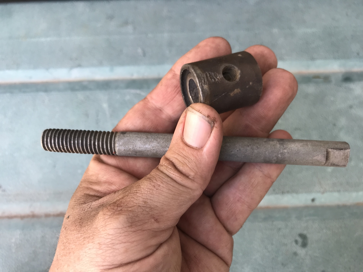
- Unusual shaft and fitting.JPG (555.04 KiB) Viewed 1375 times
Not sure if the shaft is part of this gear… looks more like a Litchfield tool.
Re: Harv's marinised grey motor thread
Posted: Tue Nov 27, 2018 12:22 pm
by Harv
The gear came with the angled carby adaptors used to mount the downdraught webers to the Repco inlet manifolds.

- Carburettor adaptors.JPG (835.43 KiB) Viewed 1374 times
I'm assuming these are used to square up the carbs because the engine is rolled to one side when it is mounted in the boat (not tilted front back, but rolled to one side). I have seen other twin Strommie manifolds from Tawco with similar angling on the carb mounting surfaces. No idea why you would roll the motor to one side in a boat instead of mounting it dead upright like a car.
The gear also came with this coupling. From what I understand, boat motors are mounted backwards, with the gearbox-end of the motor to the front (bow) of the boat. The harmonic balancer gets removed, and this coupling mounts to the crank snout. The other end of the coupling mounts to a dog clutch, and hence to the propeller shaft (big long steel shaft that goes through the rear (stern) floor of the boat). The coupling has a pulley milled into it, which I assume is used to run the generator (no fan, no normal water pump).
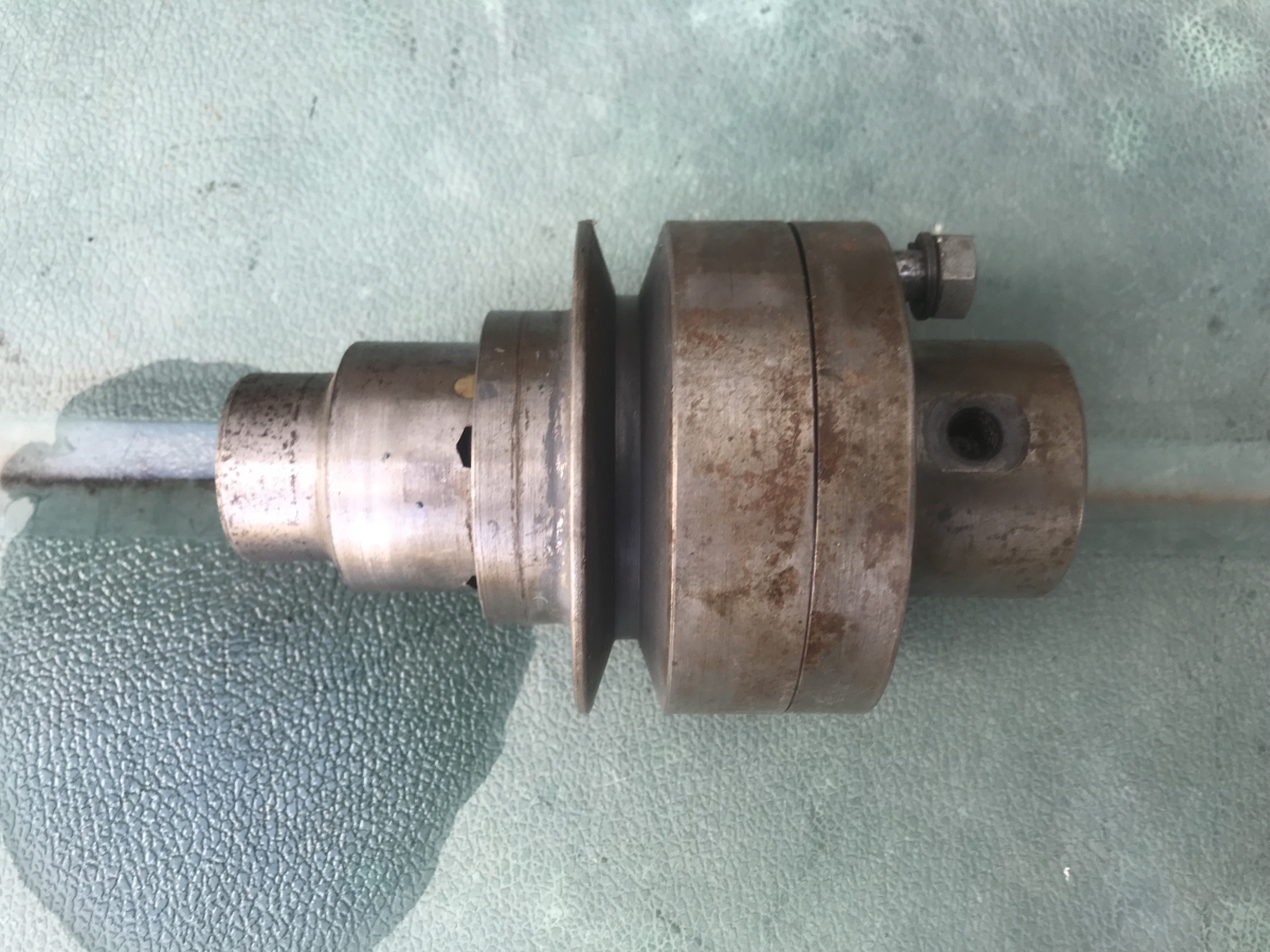
- Coupling.JPG (654.05 KiB) Viewed 1374 times
Re: Harv's marinised grey motor thread
Posted: Tue Nov 27, 2018 12:23 pm
by Harv
The Holden water pump gets removed from the engine, and this plate is used in it’s place. From what I understand, a small remote water pump is used to feed this fitting, driven off the same coupling pulley as the generator. The water pump has brass internals to try to cope with seawater corrosion.

- Water pump replacement plate.JPG (783.25 KiB) Viewed 1374 times
On the other end of the motor (now at the bow of the boat), a Hydramatic-type flexplate is used to engage the starter motor (no flywheel).
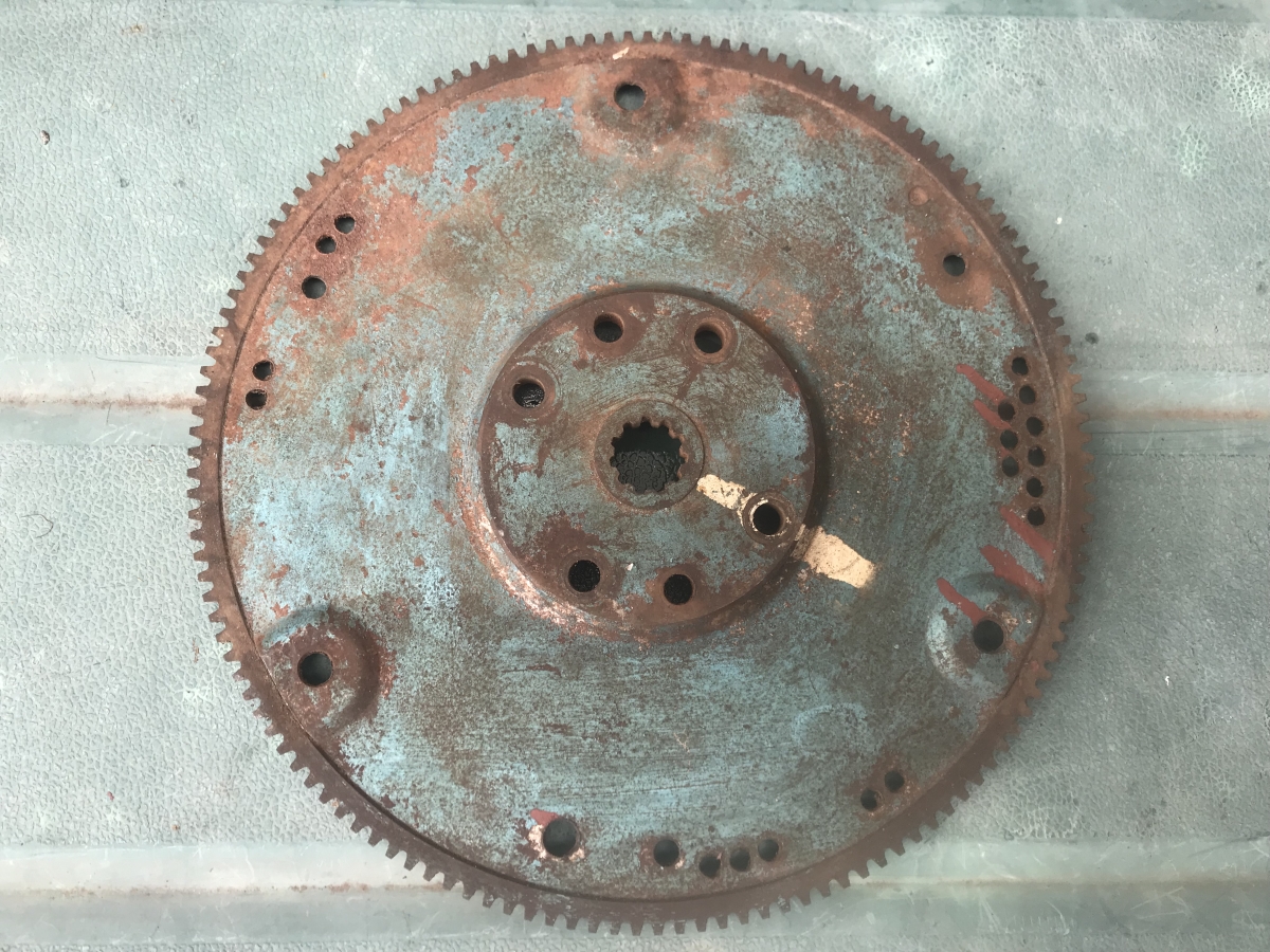
- Flex plate.jpg (909.37 KiB) Viewed 1374 times
Re: Harv's marinised grey motor thread
Posted: Tue Nov 27, 2018 12:25 pm
by Harv
The bow end of the boat has this mounting bolted on (instead of the gearbox). The mounting has two wings with large bolts either side that hold the engine to the boat hull (solid mount, not rubber mounts).
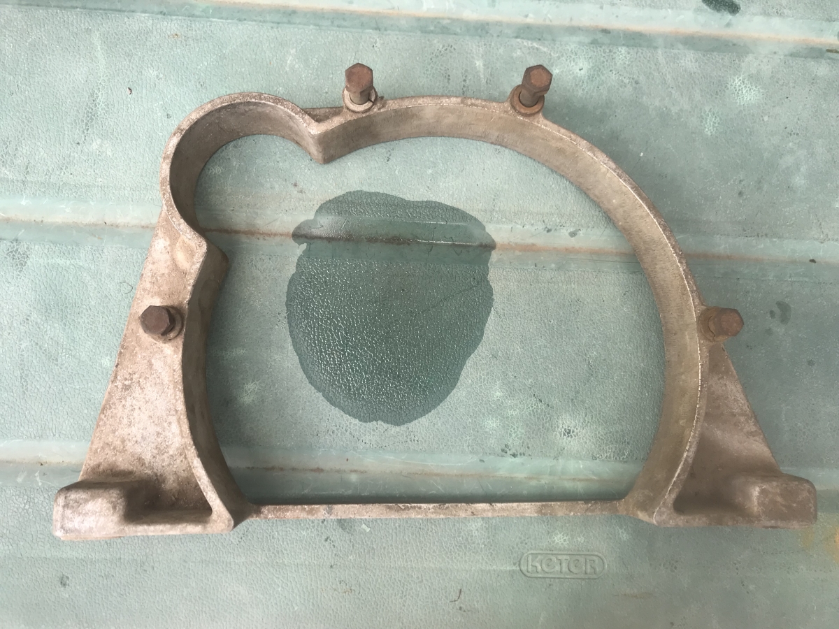
- Rear mount.JPG (762.06 KiB) Viewed 1374 times
At the stern end of the boat this fitting is used to replace the timing cover. Again, two wings with large bolts either side that solid-mount the engine to the boat hull.

- Timing cover.JPG (821.18 KiB) Viewed 1374 times
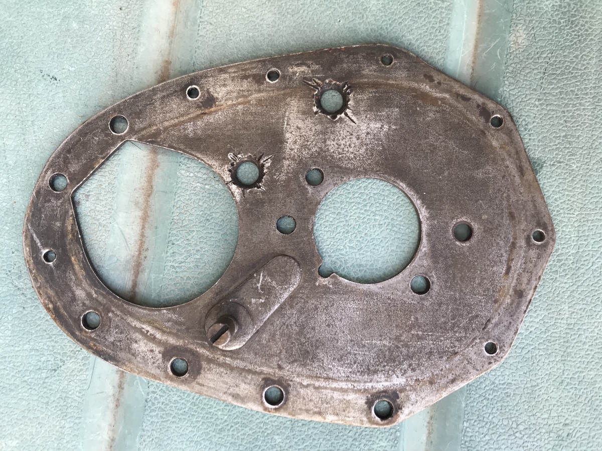
This timing cover is unusual (not standard Tawco) as it has a big hole that lines up to the end of the camshaft. The hole is used to mount a drysump pump.
- Engine front cover plate.JPG (967.98 KiB) Viewed 1374 times
Re: Harv's marinised grey motor thread
Posted: Tue Nov 27, 2018 12:28 pm
by Harv
The gear also came with an engine front cover plate (see photo above)… nothing unusual here.
The dry sump oil pump mounts to the timing cover with three bolts. A tanged drive is used to engage a slot in the end of the camshaft.

- Oil pump drive end.JPG (739.46 KiB) Viewed 1372 times
The pump is single stage. It has two ends – a scavenge end (with inlet pipe and outlet pipe), and a pressure stage (with inlet pipe and outlet pipe).
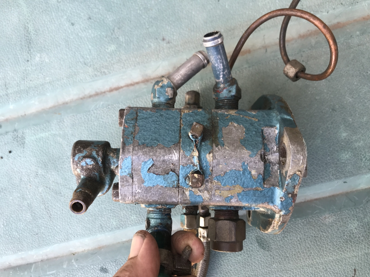
- Oil pump bottom.JPG (750.22 KiB) Viewed 1372 times
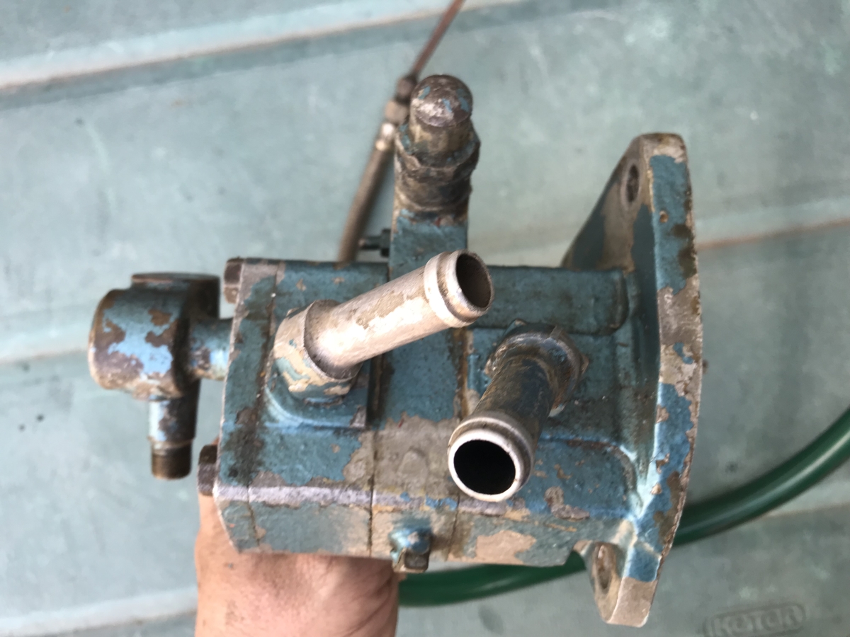
- Oil pump right.JPG (542.79 KiB) Viewed 1372 times
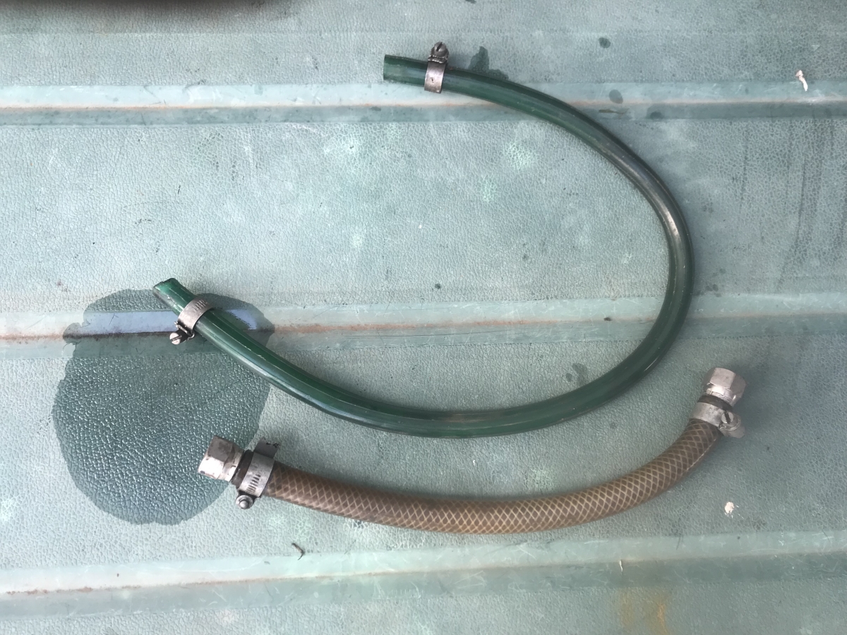
- Assorted snakes.JPG (783.2 KiB) Viewed 1372 times
Re: Harv's marinised grey motor thread
Posted: Tue Nov 27, 2018 12:30 pm
by Harv
I’ve got no idea who manufactured this pump, but would dearly love to know if anyone has any clues. No marking on the pump as far as I can see.
The scavenge side is set up to suck from the dry sump, and push oil to an oil storage tank. From there the pressure side of the pump takes suction, then pushes out through a filter and cooler before feeding the engine. The lineup is similar to what I have planned for the meth monster:
https://www.fxfjholden.com/forums/viewt ... ump#p54112
On the top of the oil pump is a relief valve, used to set the delivery pressure of oil back to the engine:
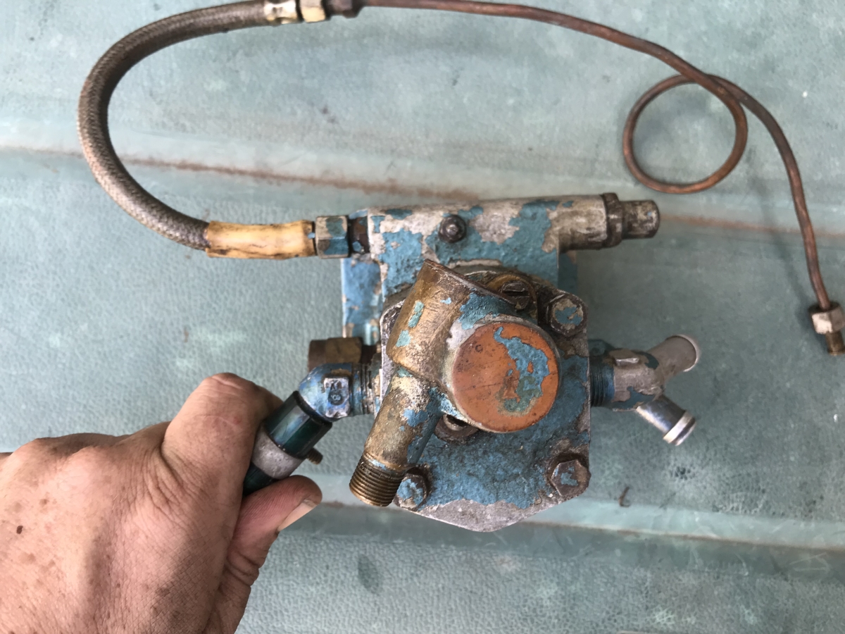
- Oil pump front.JPG (658.77 KiB) Viewed 1372 times
One side of the relief valve has a dodgy braided hose fitted, and some copper line. The copper line is feruled to connect to an oil pressure gauge.
The oil filter used as a remote setup, using a spin-on cartridge filter: The filter housing is cast “ESS” – no idea who ESS is.
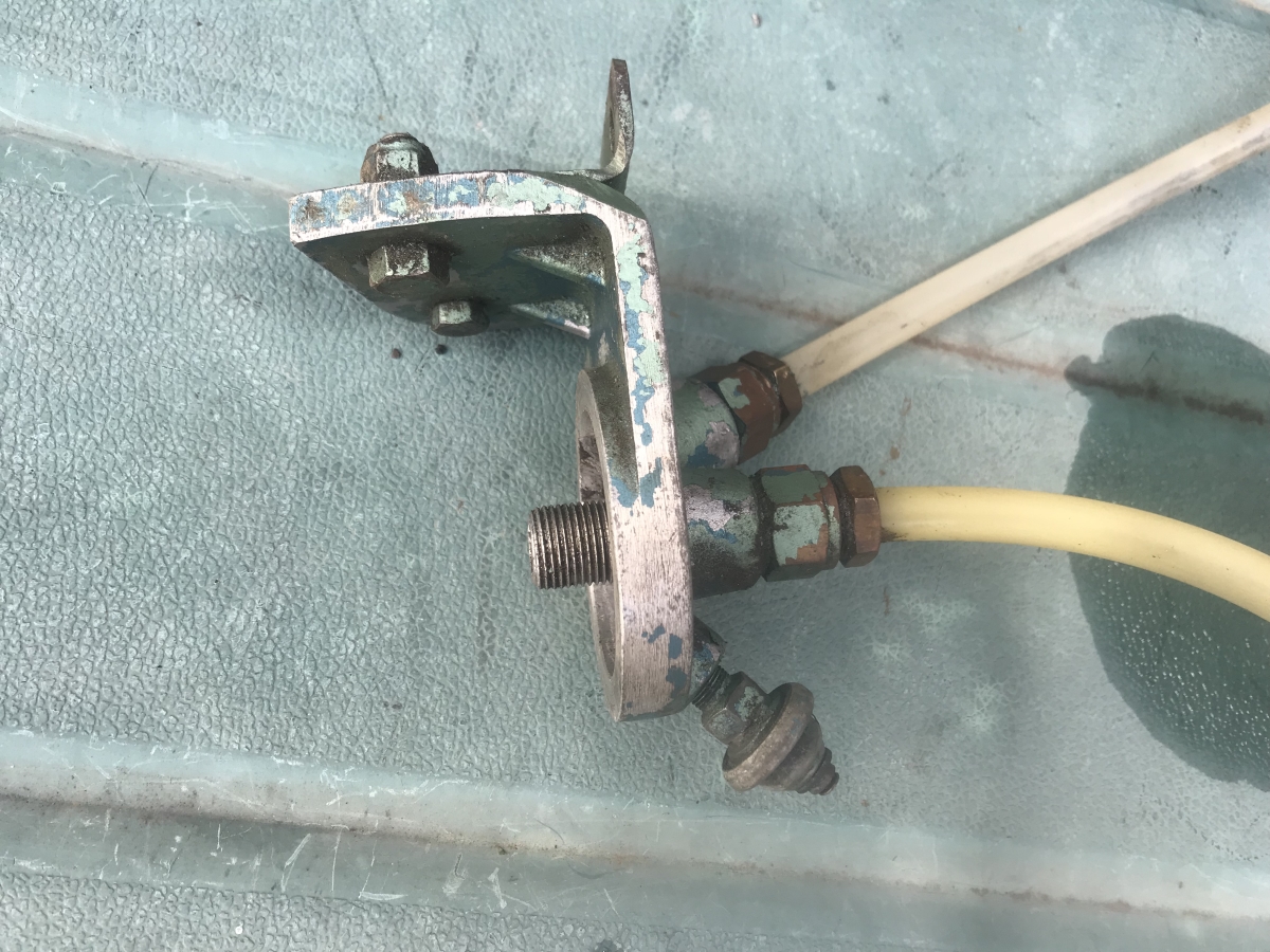
- Remote oil filter.jpg (742.54 KiB) Viewed 1372 times
Re: Harv's marinised grey motor thread
Posted: Tue Nov 27, 2018 12:33 pm
by Harv
I suspect this core was used as a remote oil cooler, though the line sizes are a bit odd.

- Maybe an oil cooler.JPG (811.6 KiB) Viewed 1372 times
The dry sump has been made by cutting down a grey motor sump. The scavenge line connects to the bottom corner (with the engine rotated, all the oil would pool in this corner).
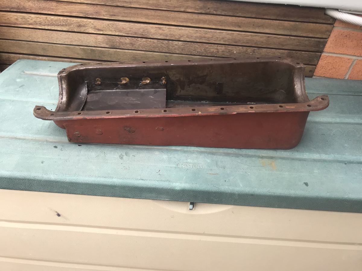
- Dry sump.JPG (651.36 KiB) Viewed 1372 times
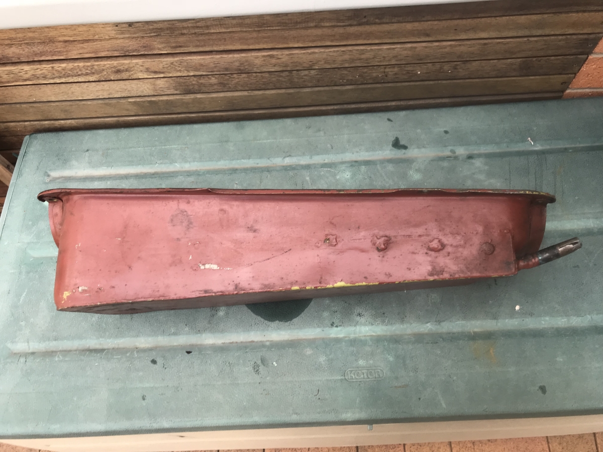
- Dry sump side view.JPG (650.49 KiB) Viewed 1372 times
A windage tray has been brazed in place (simple steel baffle)
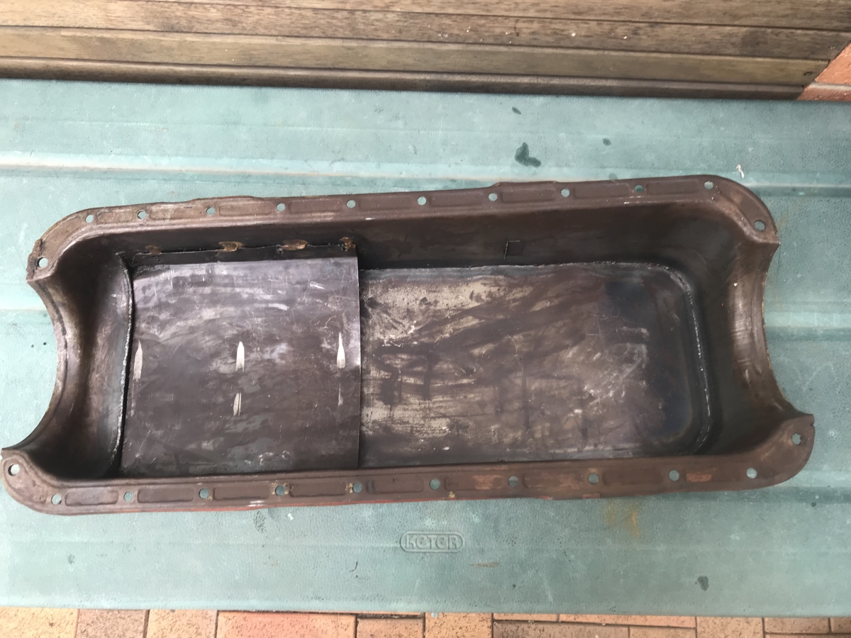
- Dry sump windage tray.JPG (666.38 KiB) Viewed 1372 times
The gear also came with this cross-shaft. I suspect this is for remote dog clutch operation, but am not sure. Can remember seeing one hanging out the back of Dave’s boat a few weeks ago, but was distracted by the big block &*#@.
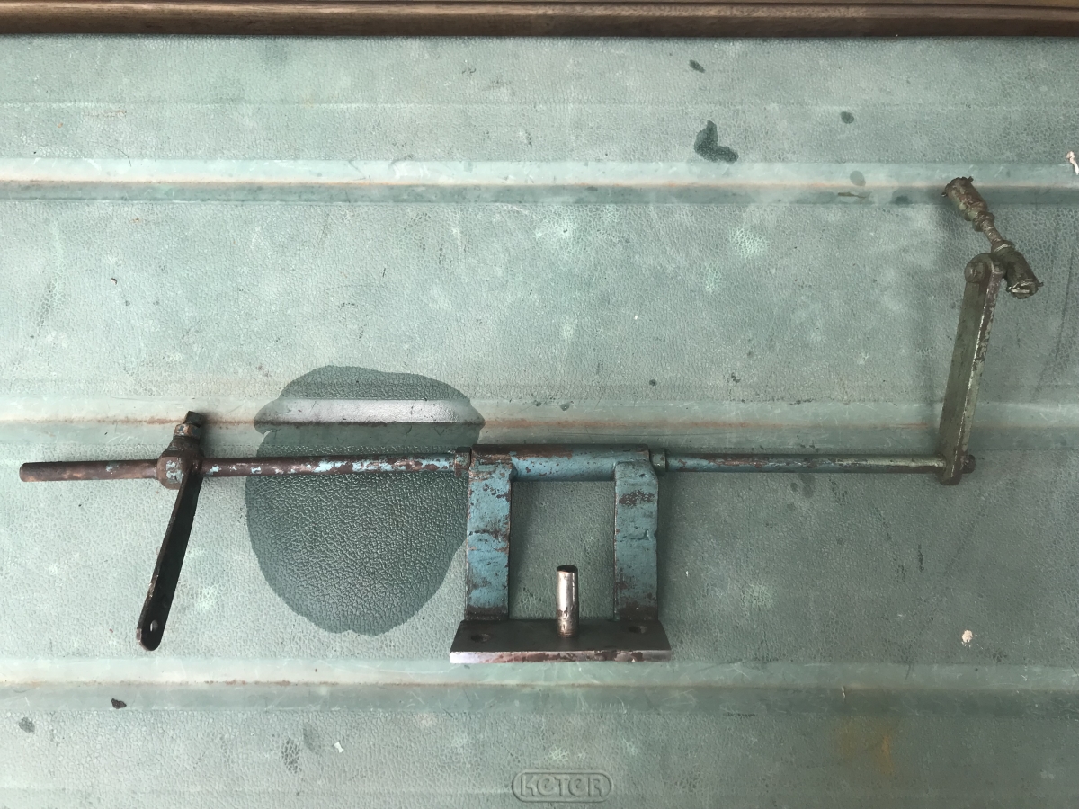
- Cross shaft.JPG (782.34 KiB) Viewed 1372 times
Cheers,
Harv
Re: Harv's marinised grey motor thread
Posted: Tue Nov 27, 2018 6:34 pm
by Errol62
My valiant enthusiast mate tells me that canting the cylinder bores counteracts side thrust and evens out wear on the bores (there was I thinking it was just done so four inches of stroke could be shoehorned into the streamlined AP5 front end lol). I don’t know if this is true and it’s probably not the reason it is done in boats. Anyway, interesting stuff Harv. Your propensity for dabbling in obscure yet Holden related stuff never ceases to astound me!!
Cheers
Clay
Sent from my iPad using Tapatalk
Re: Harv's marinised grey motor thread
Posted: Fri Nov 30, 2018 12:42 pm
by Craig Allardyce
[quote=Harv post_id=235949 time=1543281733 user_id=2189]
The gear came with the angled carby adaptors used to mount the downdraught webers to the Repco inlet manifolds.
Carburettor adaptors.JPG
I'm assuming these are used to square up the carbs because the engine is rolled to one side when it is mounted in the boat (not tilted front back, but rolled to one side). I have seen other twin Strommie manifolds from Tawco with similar angling on the carb mounting surfaces. No idea why you would roll the motor to one side in a boat instead of mounting it dead upright like a car.
Your arse about on the adapters Harv. They mount 90 degrees to the engine so the two barrel holes are side by side. The angle then corrects the carby for the engine being mounted nose down.
Re: Harv's marinised grey motor thread
Posted: Fri Nov 30, 2018 12:45 pm
by Craig Allardyce
I have an interest in these Harv as I have an old 62 Seacraft ski boat at home. Your engine appears to have possibly come from an old racing skiff being that it is fitted with a scavenge pump. Not many ski boats were ever fussed with that much. Here's a recent purchase of mine (500 bucks!).

- $_1.jpg (36.83 KiB) Viewed 1333 times

- $_57.jpg (109.43 KiB) Viewed 1333 times
Re: Harv's marinised grey motor thread
Posted: Fri Nov 30, 2018 1:43 pm
by Harv
Craig Allardyce wrote: Fri Nov 30, 2018 12:42 pmYour arse about on the adapters Harv. They mount 90 degrees to the engine so the two barrel holes are side by side. The angle then corrects the carby for the engine being mounted nose down.
You're right. I had always assumed that the Weber downdraughts were mounted to the Repco head with the two barrels running north/south. Looking at photos of original manifolds (including Dave's Bernadine boat), the barrels mount east west.
Cheers,
Harv
Re: Harv's marinised grey motor thread
Posted: Fri Nov 30, 2018 1:52 pm
by Harv
Very nice purchase

.
I wonder if the Strommies were left with the bowls to the rear of the boat, or if they were turned the other way around in most boats as the pickup is at the rear of the bowl. I'm guessing with the bowls to the rear there would be an increased risk of running the internals dry on acceleration.

- fuel level.PNG (26.82 KiB) Viewed 1329 times
Cheers,
Harv
Re: Harv's marinised grey motor thread
Posted: Fri Jan 25, 2019 10:45 am
by Harv
I took some time over Christmas to start to look at some of the marinised gear above. I started with the coupling. In theory this beastie connects the grey motor crank to the propeller shaft (it replaces the harmonic balancer):

- Optimized-IMG_0550.JPG (895.94 KiB) Viewed 1284 times
The piece on the left fits onto the grey motor crank (nearly 1” diameter bore), whilst the bit on the right fits onto the prop shaft (7/8” bore).
The interesting bit is the internals. They are splined, with round keys. The cylindrical bits are not rollers – they do not spin. Instead they are keys, used to lock the crank/prop ends together.

- Optimized-IMG_0552.JPG (708.07 KiB) Viewed 1284 times

- Optimized-IMG_0553.JPG (652.79 KiB) Viewed 1284 times

- Optimized-IMG_0554.JPG (830.93 KiB) Viewed 1284 times

- Optimized-IMG_0555.JPG (645.34 KiB) Viewed 1284 times
The splined arrangement allows the crank and prop ends to move apart by 10mm (by sliding along the cylindrical keys).

- Optimized-IMG_0559.JPG (686.32 KiB) Viewed 1284 times

- Optimized-IMG_0558.JPG (686.78 KiB) Viewed 1284 times
The sliding could be useful in splitting the coupling, but 10mm seems very short a movement to disengage a shaft. I can understand a sliding coupling is handy – it means you don’t have to be super-accurate in prop shaft length. The weird bit though is that when you slide the coupling, the pulley groove slides too. So if you had an accessory (say generator, or water pump) hung off the block, the drive pulley/belt would slide away from the accessory.
Anyone got any ideas why these things slide?
Cheers,
Harv
Re: Harv's marinised grey motor thread
Posted: Wed Jan 30, 2019 6:06 pm
by Craig Allardyce
Harv it is a thrust assembly. It has to be set up and shimmed so that all the pushing force from the propeller is taken at this point rather than at the crankshaft thrust bearings. The drawing below is a Seacraft unit.
Ideally the crank should be able to have its normal end float whilst all the propeller force is taken at the thrust housing bearing hence the sliding pins for the pulley.

- scan00052-600x469.jpg (45.02 KiB) Viewed 1251 times
Re: Harv's marinised grey motor thread
Posted: Thu Jan 31, 2019 7:24 am
by Harv
Aaahh.... thanks Craig. That makes more sense. I had assume that the propeller thrust was all taken up by the engine (come to think of it, that would be one hell of a load for the engines thrust bearings).
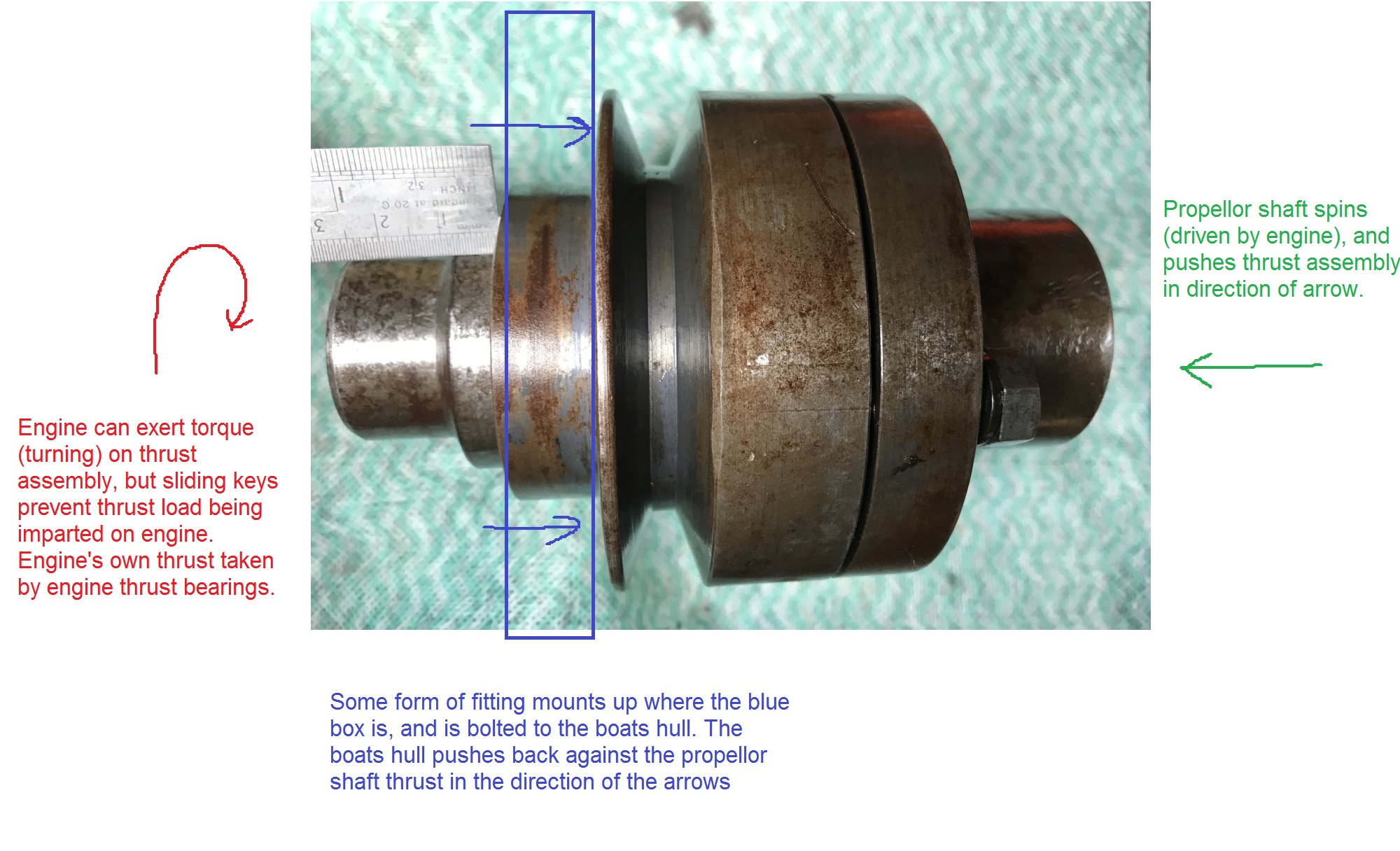
If I understand it right, is the image below correct?
Is the "blue box" part the marinised timing cover (which has wings that bolt to the hull), or is a separate assembly used?
- upload me.jpg (476.96 KiB) Viewed 1232 times
Cheers,
Harv