The challenge for today is for me to get my head around the oiling in the grey motor… with a side excursion into lifters.
The grey has a pretty simple oiling system, described in the Workshop Manuals:
A helical gear type oil pump driven at half engine speed by the distributor drive shaft supplies oil to all working parts of the engine. The pump output pressure is regulated to a maximum of 40 Ibs. per sq. in. by a non-adjustable spring-loaded plunger type relief valve located in the pump body cover. The relief valve is designed so that when the valve opens, the oil passing the valve is directed back into the intake side of the pump. The capacity of the oil pump is well above the volume of oil that is required to adequately lubricate the working parts of the engine. The oiling system is designed to meter the flow of oil to the crankshaft, camshaft, connecting rods, overhead gear and timing gears. Oil is drawn from the oil pan through a gauze strainer and then delivered by the pump through a short copper pipe to drilled passages in the rear intermediate main bearing support web. From this point it is supplied to the rear intermediate main bearing, the rear intermediate camshaft bearing and the main oil gallery. The main oil gallery extends the full length of the cylinder block and distributes oil to the remaining three crankshaft and camshaft bearings. An asbestos packing ring type seal, together with a slinger and drain, prevents the leakage of lubricant at the rear main bearing. Recessed areas on the rear main bearing cap joint face provide a reduced area of contact between the cap and the crankcase, thereby causing a greater pressure to be exerted between the mating surfaces, and effecting a more efficient sealing joint. In addition, the recessed areas act as vents between the crankcase and the crankshaft oil slinger groove, equalizing the pressures acting in the crankcase and slinger groove; this prevents the crankcase pressure from restricting the oil return from the drain back hole in the cap. The crankshaft has drilled passages leading from the main bearing journals to the connecting rod journals; these drilled passages are reduced in diameter at the connecting rod journals, thus metering the oil flow to the connecting rod bearings. The piston pins are lubricated by splash feed through a hole in the top of the connecting rod. A groove machined approximately one third of the way around the intermediate camshaft journal, collects and distributes oil to a pipe connected to a fitting where the oil is metered and further directed to the rocker arm shaft assemblies. A bleeder hole in each rocker arm supplies oil for the lubrication of the valve stems and push rod sockets. Lubricant for the timing gears is supplied from a drilled passage between the oil gallery and the front main bearing. The oil is conducted from this point through a formed channel in the rear surface of the front engine plate to a metering nozzle extending out from the front of the plate. The oil stream from this nozzle is aimed to lubricate effectively the timing gears. A spring loaded synthetic rubber oil seal is pressed into the recessed opening in the timing gear cover to prevent oil leaks from around the hub of the harmonic balancer. Provision has been made for the fitting, as an accessory, of a by-pass type oil filter for operating conditions such as those involving sludging or dust.
My intention is to fit a dry sump to the meth monster motor. Why? There are some horsepower gains to be had (from less oil mist bouncing around in the crankcase)… but mainly because I have the bits, and like the idea of running one. The overall layout of the system is as per below:

- dry sump plumbing.png (20.6 KiB) Viewed 1020 times
In simple terms, the GMH oil pump gets removed from the grey, and it’s discharge port blocked off inside the block. An external pump then takes suction from the sump, and a heap of fancy kit is used to clean, store and pressurise the oil before returning it to the motor. The diagram below gives you some idea of what this looks like – standard grey motor on the left, dry sump on the right:

- Drysump oil flow to oil users.png (593.78 KiB) Viewed 1020 times
Note that the image on the right shows a shallower oil pan (that’s the plan), but shows a heap of “red” oil in it. In reality, the pan will be nearly dry, with the external oil pump scavenging as much as it can.
There are some bits of the lubrication process that do not change:
a) Oil is pressure fed to the crankshaft, camshaft and connecting rod bearings and rocker arm shaft assemblies.
b) Oil is dribbled over the valve stems and push rod sockets.
c) Oil is squirted onto the timing, distributor and cam gears.
One bit that worries me though is that the piston pins (con rod little ends) are lubricated by splash feed through a hole in the top of the connecting rod:

- Little end lubrication.png (21.22 KiB) Viewed 1020 times
With the dry sump aiming to cut down on oil mist, there is a chance that the little ends run dry. There are a couple of options to deal with this:
a) Do nothing, and prey there is still enough oil floating around the crankcase to lubricate the little ends,
b) Install oil squirters. These are small nozzles that tap off an oil gallery, and squirt a jet of oil up under the piston crown. Good for lubricating the little end, but also good for cooling piston crowns.
c) Drill the conrod lengthwise: through the big end bearing, up the length of the conrod, and into the little end bearing. This provides pressure feed to the little end, as per the picture at the bottom of this post (yeah, I know it's out of order... can't work out why).
I'm not too sure which of these three options to take. Methinks I need to ask the lumpy humpy crowd, and see if any of them have dealt with dry sumped little end oiling.
The second it that worries me a little is the lifter oiling. In the standard grey motor, oil flows from the rocker tips, down the pushrods and into the lifter cups. According to the diagrams above, the lifter cups have a drain hole, which allows oil to flow into the lifter bores (it squeezes out between the lifter and the bore wall). The oil then falls out the bottom of the lifter bore into the sump, splashing over the cam lobe faces as it falls. I've taken a good look at the lifters in the FB, and I'm pretty sure there is no oil drain hole in them. I suspect the GMH diagram above is a bit optimistic, and in reality the oil splashes out of the lifter cup and onto the lifter bore (rather than out a drain hole).
While I am thinking about lifters, in an ideal world, I could use standard lifters (and hence have standard lifter oiling). Of course, if you are as silly as I am then you gave away your last set of grey motor lifters to help a bloke out. I can try to hunt down some standard grey motor lifters…… or I can do something funky. Talking to the lumpy humpy crowd, &*#@ 302 lifters have the same bore as a grey motor lifter (0.874”). The pictures below show a 302 &*#@ lifter (Speed Pro part number SPAT2000) alongside a standard grey motor lifter.
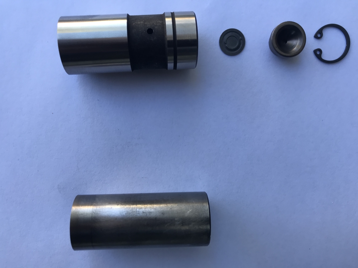
- 302 versus grey motor lifter.JPG (463.67 KiB) Viewed 1020 times
The 302 lifter has a removable seat (held in place with the circlip). The small metal disk is a check valve. The 302 Fords take pressurised oil from the lifer bore, feed it past the check valve, up the hollow pushrod and use that oil to lubricate the rockers. If I used the 302 &*#@ lifters, oil would fall down the pushrod and sit on the closed check valve... no different to a standard lifter. There is also the option to remove the check valve and have the oil drain out the oil hole to the lifter bore. Dimensionally, the 302 &*#@ lifters are different:
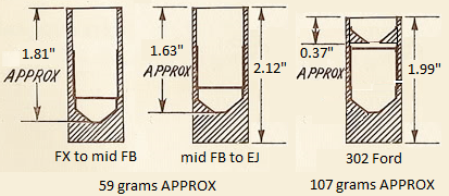
- 302 lifters.png (73.17 KiB) Viewed 1020 times
Not a big drama if you are using custom pushrods. I suspect the pushrod end on the &*#@ is slightly different to the grey motor, as grey motor pushrods tend to foul on the 302 &*#@ lifter circlip. What gets me though is that the 302 &*#@ lifters are nearly double the weight of the grey motor lifters. Not a good thing for something that is reciprocating at a bazillion miles an hour. Methinks I'll stick to the standard grey lifters... just gotta find a set

.
Cheers,
Harv
327 Chev EK wagon, original EK ute for Number 1 Daughter, an FB sedan meth monster project and a BB/MD grey motored FED.