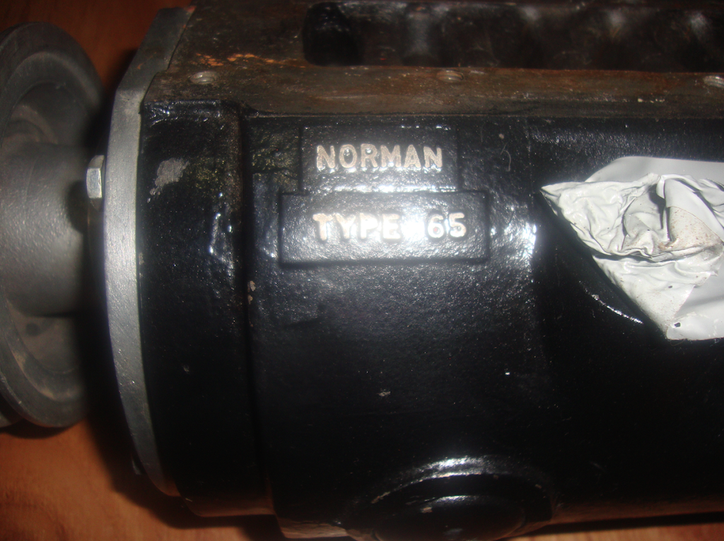
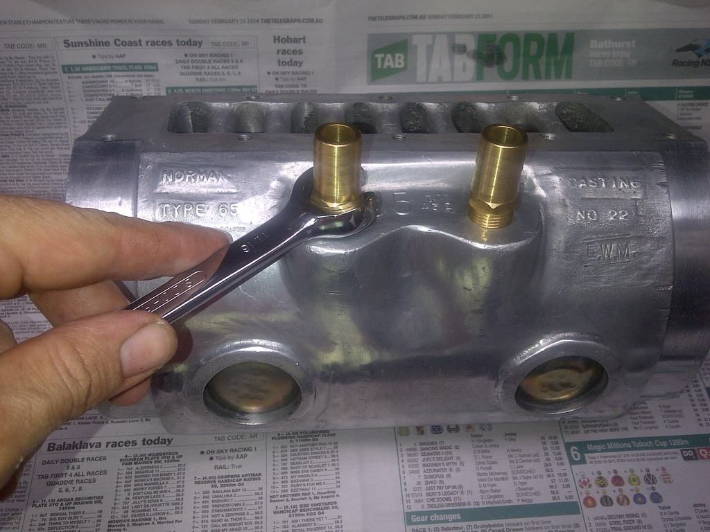
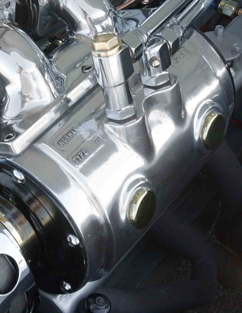
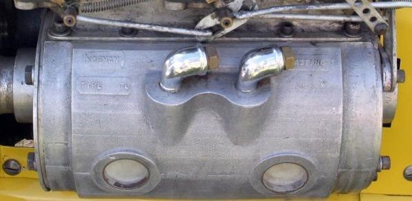
Ladies and gents,
In the post below, I am going to cover the way that the ignition system can be changed to reduce knocking (pinging) in our supercharged grey motor. By retarding the timing, the engine will have less tendency to knock.
Our standard Holden grey motor has three separate components to ignition timing:
a) Advance which is added by rotating the distributor then bolting it down. This is often referred to as “flywheel advance”, and is constant regardless of what the engine is doing. For a grey motor, this is typically 2º.
b) Mechanical advance (sometimes called centrifugal advance). This is accomplished inside the distributor by a combination of spinning weights and springs, and varies with engine speed. It works by rotating the top of the distributor shaft clockwise to open the points earlier. For a grey motor, the following is a typical mechanical advance curve:
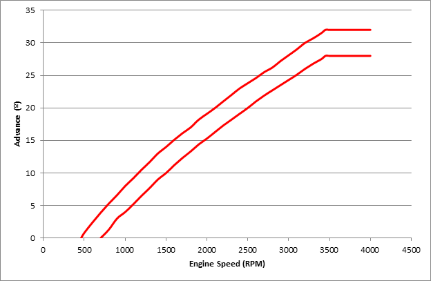
Note that there is a range of advance for a given engine speed (between the two red lines), as not all distributors are quite the same. The faster the engine spins, the more the distributor advances the timing (up to 28-32º at 3450rpm). The mechanical advance component can thus be described as “28-32º all-out at 3450rpm”.
c) Vacuum advance. This is again accomplished inside the distributor, but is driven by the vacuum module sitting on the side of the dizzy. The module is connected to the inlet manifold – the more vacuum in the inlet manifold, the more the vacuum module advances the timing. It works by rotating the breaker plate (and the points attached to them) anti-clockwise to open the points earlier. For a grey motor, the following is a typical vacuum advance curve:
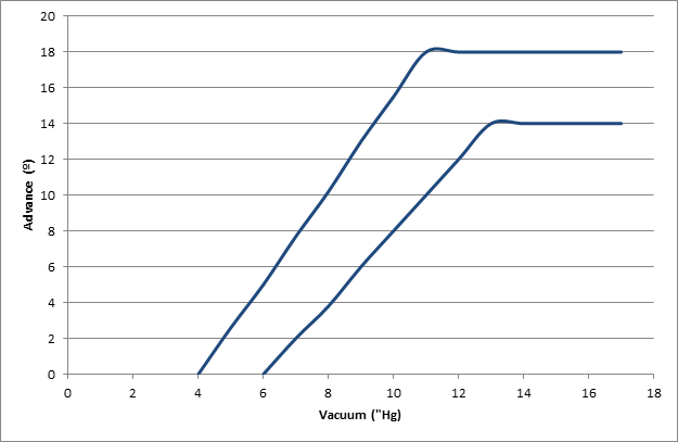
Note that there is again range of advance for a given vacuum (between the two blue lines), as not all distributors are quite the same. The higher the engine vacuum, the more the distributor advances the timing (up to 14-18º at 10-12”Hg of vacuum).
The total timing advance we get is thus a combination of flywheel advance (how far the dizzy body is turned), mechanical advance (how far the dizzy shaft top is turned) and vacuum advance (how far the points are turned), and depends on both engine speed (rpm) and load (vacuum). This needs thinking through in light of supercharged operation.
So just how much advance do we need for our Norman-blown grey, and how do we set it up?
Our first option (Option 1) is to rely on flywheel and mechanical advance alone, and set them up so that they do not offer too much advance as boost increases. From Supercharge!, we can see the following advice:
a) For every degree of “effective compression ratio” increase, retard the timing by 3º (for example, an engine on 9:1 might require 40º advance at peak r.p.m., whilst the same engine on 12:1 would only require about 32º). “Effective compression ratio” is a calculated number which tries to blend together an engines normal compression ratio with the “squeeze” obtained by supercharging. Effective compression ratio can be calculated as:
Effective compression ratio = √((Boost+14.7)/14.7) x static compression ratio
For example, a vehicle running 5 psi boost with a static compression ratio of 8.8:1 gives:
Effective compression ratio = √((5+14.7)/14.7) x 8.8 = 10.2
Note that Weiand use a different formula:
Effective compression ratio = (Boost/14.7+1)x static compression ratio
This gives a different result to Eldred’s method (for example, our 5 psi/8.8:1 vehicle would return an effective compression ratio of 11.

. The difference in calculation is something to be mindful of (for example if the effective compression ratio table in the Weiand Supercharger Installation Instructions Part A are used).
b) Undertake the timing reduction by reducing centrifugal advance, not by reducing flywheel advance (i.e. by regraphing the distributor, not by rotating the distributor).
c) Retard the distributor itself approximately 4º in addition to allow for decreased octane.
An additional set of advice is given by Weiand:
“We have achieved our best results with 12 to 20° of initial lead with a total lead of 32 to 36°. The advance should be in by 2,000 to 2,500 rpm... We have found that for all of the engines that we have dyno-tested, that the best power is obtained with 32° of total spark advance, with the entire advance coming in by 2,800 rpm. This is the maximum power with 108-octane race gasoline. You will probably not be able to use this much advance with pump gasoline. Our tests have shown that dropping the total spark advance back to 25° results in a loss of only two percent of power and torque up to 4,000 rpm and four percent of power and torque at 5,500 rpm. For this small loss in power, there will be a considerable reduction in detonation.” - Weiand Supercharger Installation Instructions Part A.
Weiand’s advice is consistant with guidance from other sources, for example:
“For most applications, the distributor should have a centrifugal advance mechanism set up so that the entire advance is in by 2,500 rpm. Typically, 34 degrees should be a safe level of ignition lead to provide close to optimum performance.” – Chevy High Performance Magazine
We can cross-check the Weiand guidance against Eldred’s views. If we take a grey motor running 7.25:1 static compression and add 10psi of boost to it, Eldred calculates
Effective compression ratio = √((10+14.7)/14.7) x 7.25 = 9.4
This is an increase of (9.4 - 7.25 = ) 2.1 degrees of compression, to which Eldred would recommend (2.1 x 3 = ) 6½ degrees of centrifugal advance timing reduction, plus up to 4º of static advance reduction. Our factory grey motor running flat-out has 32º of centrifugal advance, which we would reduce to 25½º. We also have 2º at the flywheel which would be reduced by around 4º, giving a total of 23½º total advance. This is pretty close to the guidance given by Weiand (around 25º total advance). As an interesting aside, early VW’s typically started with timing of 10º flywheel advance, and around 26º of vacuum advance (no mechanical) to give 36º total. This was tuned for the Judson supercharger by reducing flywheel advance by 5-7½º to give 28½-31º. This is again similar to Weiand’s advice.
So as a practical guide for setting up supercharged timing for a grey motor under Option 1, the following is a starting point:
a) Disconnect the vacuum advance and plug off the inlet manifold connection.
b) Regraph the distributor to give the following centrifugal advance, all-in at 2500rpm:
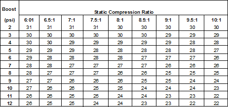
If you are unsure as to your compression ratio (say because the head has been worked) or boost level, then aim for 25º centrifugal advance, all-in at 2500rpm,
c) Set flywheel advance at 2º, and reduce/advance as necessary (probably 1-4º) to reduce knocking.
Option 1 is thus dependant on a particular engines boost/compression, but in summary uses no vacuum advance, changes mechanical advance from “28-32º all-out at 3450rpm” to (roughly) “25º all-out at 2500rpm” and tunes using the flywheel advance.
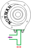
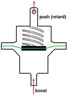
Our second option (Option 2) is to try to get full advantage of the mechanical advance, yet reduce timing as boost increases. We could do this with an electronic boost retard box, though this is not too period-correct. One way to do this is to utilise boost retard in a manner similar to vaccum advance (i.e. by rotating the breaker plate inside the distributor - kinda like vacuum advance in reverse). This is not as simple as just connecting up the factory Holden grey motor vacuum advance unit to boost pressure due to the internal configuration of the unit. As can be seen from the diagram below of the factory unit, vacuum acting on the green diaphragm causes a compression spring to compress, pulling on the rod to advance timing. Adding boost to the factory grey motor unit tries to make the spring stretch, bottoming out the unit.
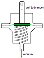
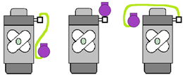
What we are looking for instead is a setup similar to that shown below.
As an aside, this type of boost retard should not be confused with vacuum retard where timing is retarded with increasing vacuum, not boost. Vacuum retard is an evil process used as an emissions control device (lowering NOX emissions by dropping combustion temperature) in vehicles like the 1971-1976 Triumph TR6 and 1969-74 Jaguar Series ll and XJ6. As an example of a vehicle that did use the type of boost retard we are looking for, Chevrolet released the Corvair Spyder from 1962 with a 150hp turbocharged option. This vehicle did not use vacuum advance, but instead used a similar type of diaphragm module to measure boost. As boost increased, timing was decreased. Timing for the Corvair Spyder was as follows:
a) Flywheel: 24º
b) Centrifugal: 10-14º all in at 4500rpm
c) Boost retard: 7.5-10.5º per psi, all in at 1.5-2.5psi.
Thus a Corvair Spyder motor operating at 4500rpm and 2.5psi boost would have ignition timing of 24+10-11 = 21-23º. This is pretty close to the guidance given above by both Weiand and Eldred.
In Supercharge!, Eldred mentions this type of boost retard unit, indicating:
“It is difficult to get the correct spring tension and amount of travel correctly balanced with the boost pressure. However for those interested in trying this a total movement of the plate mounting the points, in the region of six degrees of the distributor will cope with an eight pound supercharge. The distributor itself will have to be advanced about eight degrees over the normal setting to compensate for the total loss of what was formerly the vacuum advance mechanism.”
In summary, Option 2 uses factory mechanical advance, reduces timing with increasing boost, and tunes with flywheel advance. Without using a boost retard box, Option 2 is not an easy one to pursue.
Option 3 is a simplistic version of Option 1, and is used by many race vehicles. This involves locking the distributor. Locking the distributor means that both the vacuum advance and flywheel advance are disabled, and all timing is done by changing the flywheel advance. The advance/static compression ratios shown for Option 1 can be used (or the simplistic 25º advance used as a starting point). Locking the distributor makes it’s operation more simple (and hence more reliable), though means that all the advance the car needs comes on at very low rpm and is fixed. This is OK for a car that runs flat-out all the time (like speedway or drag cars), but not so good for cars that operate over a wide range of speeds and loads (like your typical road car). At low rpm, a fixed-timing road car can perform quite poorly. Another drama of fixed timing is that it gives waaaaaay too much advance at startup compared to a “normal” engine. When cranking over the engine, the engine may fire the charge early (especially if the engine is hot), making the piston push backwards. This can break teeth from the starter or ring gear. One way around this is to install an ignition isolation switch inside the cabin, in parallel to the factory Holden key-switch. Turn the ignition isolation switch to off (ignition off, no spark) until the motor is cranking over strongly (2-3 seconds) then flip the ignition system back on.
In summary Option 3 is simple and reliable (lock the advance at roughly 25º)… just not well suited to anything that runs other than flat-out the whole time.
Whilst the above deals with mechanical and flywheel advance, we also need to think about vacuum advance. Opinions vary greatly as to the need for it in supercharged vehicles. For example:
a) Moss and Judson both recommend using vacuum advance with their superchargers,
b) Holley (Procharger) provides for a vacuum advance connection in their supercharger manifolds,
c) Several of the MSD Ignition boost retard units allow for programmable vacuum advance, and
d) Shorrock disconnected vacuum advance with their superchargers.
Generally, the supercharged engine will still develop vacuum (not boost) under cruise conditions, and vacuum advance can be useful for throttle response and fuel economy. Our first option for vacuum advance is to simply disconnect the vacuum advance and block off any connection on the inlet manifold. This is simple and cheap, though does sacrifice some throttle response and fuel economy.
Alternatively, we can look at There are two positions we can take our pressure/vacuum signal from:
a) Ported vacuum – this is taken upstream of the carburettor(s) butterfly and will always be vacuum (never pressure), or
b) Inlet manifold – this is taken between the supercharger and the cylinder head, and will vary from vacuum to pressure depending on engine load.
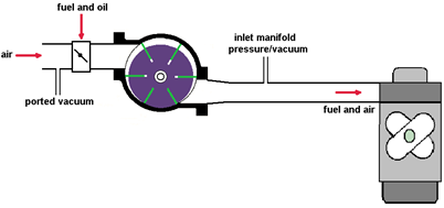
The two different locations will vary in pressure/vacuum as follows:

Note that this will vary slightly with configuration – for example if the carburettor is too small, then vacuum will be higher (lower pressure) at the inlet manifold but lower (closer to zero) at the ported vacuum connection.
If the standard ported vacuum connection location is used to set the timing, the distributor will still see vacuum under off-idle and cruise conditions (and advance the timing) – no harm there. However, as engine load (and hence boost) begins to increase, the distributor will continue to see vacuum, increasing timing (by up to 18º for a standard grey motor vacuum unit and distributor!). Advancing the timing with increased boost will cause substantive knocking.
Vacuum advance can be plumbed into the inlet manifold. In this location, the unit will see vacuum under off-idle and cruise conditions (and advance the timing). As engine load (and hence boost) begins to increase, the distributor will see boost (an absence of vacuum) and will reduce the (vacuum) timing advance to nil. The problem in doing this though is that at idle the distributor sees vacuum and retards timing. This can give a significant bog when you first put your foot down.
Whether or not we choose to use vacuum advance, we may wish to check the mechanical advance curve. Without putting the distributor on a regraphing machine, you can check the mechanical advance curve by marking the flywheel. The normal process for setting ignition timing utilizes a timing light. The light is connected to cylinder #1, and the engine allowed to idle at 480-520rpm. At this speed, a typical Holden grey motor should have zero (at most 1º) mechanical advance. Early Holdens were designed to run timed spark vacuum (the vacuum port connection is at the throttle body above the throttle plate), giving no/little signal to the vacuum advance module at idle (and hence no vacuum advance). Thus at idle we are really only checking the flywheel advance. For our Holden grey motor, when the timing light flashes it is aimed at the timing ball on the flywheel. The ball is located at 2º flywheel advance (note that the flywheel also has a “UC” mark a little anti-clockwise, which marks Top Dead Centre, or 0º advance). So our timing light is really checking that we have 2º of flywheel advance in our standard grey motor. The grey motor flywheel ring gear has 113 teeth (roughly 1/3 of a tooth per degree). Thus if we flash the timing light at more than 3450rpm, the dizzy should have advanced the timing 28-32º, or 9-10 teeth clockwise. To check the advance, put a series of coloured dots (with paint) under the flywheel teeth e.g.
0º mechanical advance = factory steel ball.
5º mechanical advance = red paint dot = 1.5 teeth to the right (clockwise) of the factory steel ball.
10º mechanical advance = blue paint dot = 3 teeth to the right of the factory steel ball.
15º mechanical advance = white paint dot = 5 teeth to the right of the factory steel ball.
20º mechanical advance = green paint dot = 6 teeth to the right of the factory steel ball.
25º mechanical advance = yellow paint dot = 8 teeth to the right of the factory steel ball.
30º mechanical advance = purple paint dot = 9 teeth to the right of the factory steel ball.
You can then run the car up to a given rpm, flash the timing light and see how much advance you’ve got by looking at what coloured dot is illuminated.
At some stage I’ll come back to ignition timing and post more – I currently know how to simply limit vacuum advance, but want to play around a bit more with mechanical advance in the standard GMH dizzy. The aim is to give a simple, no welding, backyard way to setup the dizzy for a supercharger. Watch this space.
Cheers,
Harv (deputy apprentice Norman supercharger fiddler).
327 Chev EK wagon, original EK ute for Number 1 Daughter, an FB sedan meth monster project and a BB/MD grey motored FED.
