rewiring engine bay

-
mattymartin
- Posts: 841
- Joined: Fri Oct 06, 2006 12:49 pm
- State: NOT ENTERED
- Location: sydney
terminal blocks...
thanks mod,
terminal blocks... there now gone... use spade connectors to replace terminal block...
here's the left side done...

that terminal will hoprfully budge this weekend as it had liquid spanner soaking in all week...
does anybody know what a junction is...
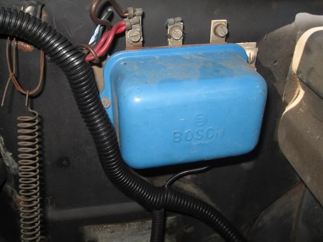
because after showing an autoelectrician this picture & a breif description on what going on... the bloke said that all i need to do, was create a junction, joining the red & the brown wires...
this sunday & monday i'll be back in to it but this weekend i'll finish it... 7am - 7pm each day...
wish me luck
matty martin
terminal blocks... there now gone... use spade connectors to replace terminal block...
here's the left side done...
that terminal will hoprfully budge this weekend as it had liquid spanner soaking in all week...
does anybody know what a junction is...
because after showing an autoelectrician this picture & a breif description on what going on... the bloke said that all i need to do, was create a junction, joining the red & the brown wires...
this sunday & monday i'll be back in to it but this weekend i'll finish it... 7am - 7pm each day...
wish me luck
matty martin
Last edited by mattymartin on Wed Sep 26, 2007 11:00 pm, edited 1 time in total.
go the wagons....

-
smooth
I thought the plan was to hide all the wiring? All I'm seeing is black plastic tube. ..... and that's fine for protection when you hide the wiring under the guard.
Your auto elec is telling you to join the wires all together that are going to the regulator on the wiring wall. Join them like all the others and tape them back into the harness. I hope you are soldering and heat shrinking all the joins and soldering on the "spade" connectors. Crimping just won't cut it after a while.
Regards, Smooth
-
mattymartin
- Posts: 841
- Joined: Fri Oct 06, 2006 12:49 pm
- State: NOT ENTERED
- Location: sydney
spade connectors
thanks guys,
hey smooth, "I thought the plan was to hide all the wiring? All I'm seeing is black plastic tube. ..... and that's fine for protection when you hide the wiring under the guard".
i've only done the left hand side in the photo so far...
can you explain how to solder on the spade connectors...
also i'm having a bit of a dilemma on how to join three ends... i'm assuming that i first cut & solder the red one so it one straight piece or wire then find where they end & join them... 
thanks
matty martin
hey smooth, "I thought the plan was to hide all the wiring? All I'm seeing is black plastic tube. ..... and that's fine for protection when you hide the wiring under the guard".
i've only done the left hand side in the photo so far...
can you explain how to solder on the spade connectors...
also i'm having a bit of a dilemma on how to join three ends... i'm assuming that i first cut & solder the red one so it one straight piece or wire then find where they end & join them...
thanks
matty martin
go the wagons....
-
mattymartin
- Posts: 841
- Joined: Fri Oct 06, 2006 12:49 pm
- State: NOT ENTERED
- Location: sydney
also...
hey team,
what have you used to attach the wires to the guards... i mean in the way of brackets, clips etc...
matty martin
what have you used to attach the wires to the guards... i mean in the way of brackets, clips etc...
matty martin
go the wagons....
-
mattymartin
- Posts: 841
- Joined: Fri Oct 06, 2006 12:49 pm
- State: NOT ENTERED
- Location: sydney
roscos reply
thanks for you reply mate,
firstly i'm not to familar with some of the terms used in auto electrics... so some of it didnt make sense to me...
where possible could you show me some pics
so i have some questions... sorry
1. i got copper wire... is this ok, also the old wire is silver... will this work ok together...
2. i also would love to no joins but i cant find where the wires start from...way up under there... and as its my first attempt at do any sort of electrical i thought i would keep it as basic as possible...
3. sorry gotta go will finish tonight..
matty martin
go the wagons....