Harv's grey motor magneto thread
Re: Harv's grey motor magneto thread
Ladies and gents,
The magneto test set-up is making some progress, albeit slowly. For the spark plug rack, I got all six candles mounted, using grey motor BP5S plugs. Remember that I need a huge gap, around 0.3125”, to overcome the fact that we are testing at atmospheric pressure. The BP5S plug gap won’t open that far… in fact, even if you grind away all of the earth electrode the biggest gap you can get is 0.175” (this is where the centre electrode arcs to the threaded portion of the sparkplug). To overcome this, I threaded the plugs into the rack, then die-ground the threaded portion back to expose the (insulated) centre electrode – see photo below:
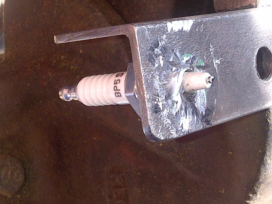
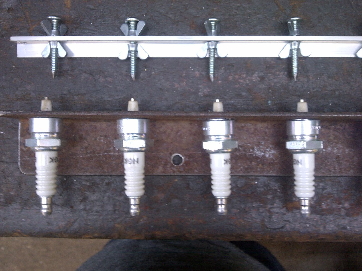
With this setup, the distance from the uninsulated portion of the centre electrode to the rack is 0.37”. If I don’t supply some other form of earth elecrode, the centre electrode will arc the 0.37” distance back to the rack (i.e. the maximum plug gap with this setup is 0.37”, more than the 0.3125” that I need). To make the plug gap adjustable, I made a rack of earth electrodes. The earth electrodes are made from gutter bolts (love those wing nuts), with the tips ground to a point. By adjusting them up and down I will be able to set the gap accurately on each plug.
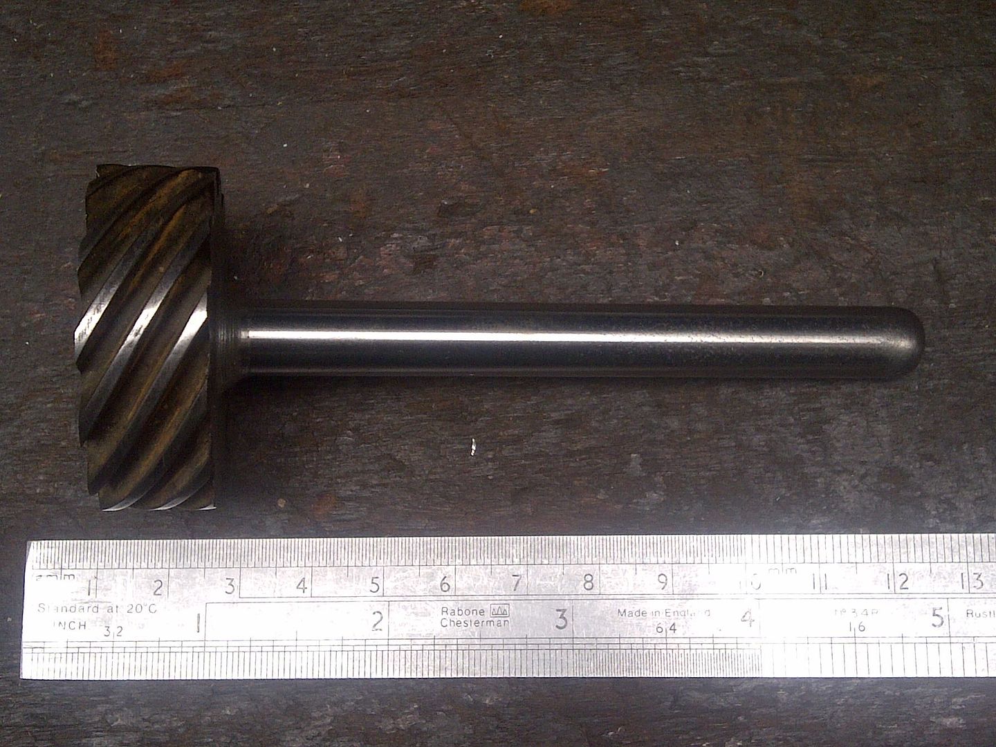
I also received the drive gear and spindle, which has been turned down from a grey motor camshaft (many thanks again Mr Brown).
Mounting this in my drill press, I’ve been able to dummy up some brackets, and have successfully spun a grey motor dizzy. The bracketry needs a bit more work, but for now I’m happy – I’ve got a 16 speed dizzy/magneto tester .
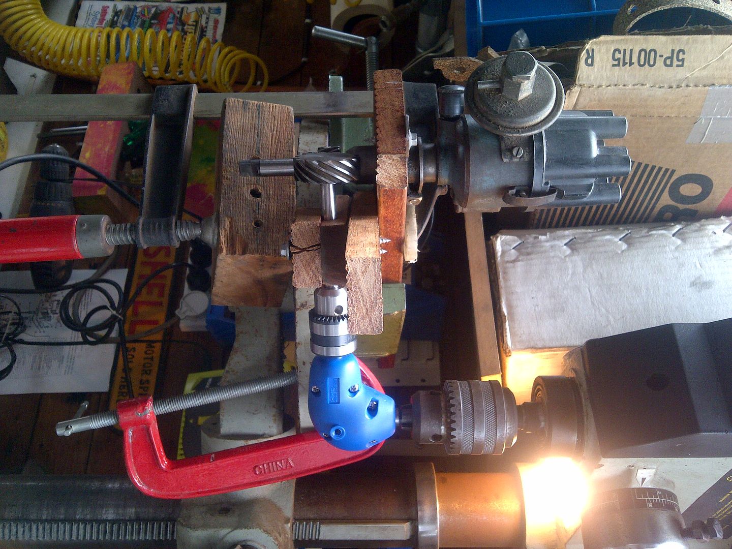
Not the best photo in the world, and sideways but you get the idea.
On the oscilloscope front, I’ve bought some test probes, which turned into a pretty major drama for something so simple. The store initially had none, and had to order them in. They arrived… and were two different probes (they need to be identical to assist in calibrating the oscilloscope channels, especially as I don’t have any calibration tools). The store was pretty good about it, and ended up mailing two identical probes to me. I’ve still got some learning to do (sadly my oscilloscope training material, purchased from the US, disappeared in the post… hopefully the resent materials get to me soon).
On the positive side (and after Mr Brown reminded me), I did get my tin-foil hat made. The purple loop keeps the Zim Pirates away…
Just gotta work out the lightning rod for the shed.
Cheers,
Dr Frankenharv.
327 Chev EK wagon, original EK ute for Number 1 Daughter, an FB sedan meth monster project and a BB/MD grey motored FED.
Re: Harv's grey motor magneto thread
I can imagine the sparks ! Top work very interesting
Re: Harv's grey motor magneto thread
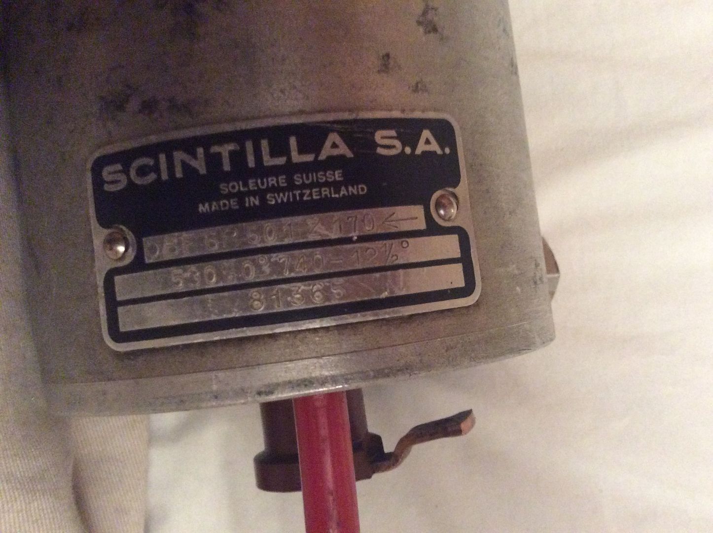
The photo below shows an interesting 6-cylinder Vertex magneto. I thought I’d post it here as a word of warning to those thinking of buying a Vertex and slapping it onto a grey – not all Vertexs are the same internally.
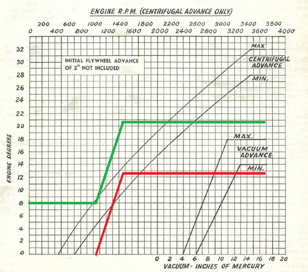
From the nameplate, we can see that the mechanical advance will start (0º) at 1060rpm, and wind up to 12½º of advance at 1480rpm. Remember from earlier posts that the rpm indicated on a Vertex nameplate is the magneto rpm, and must be doubled to give engine rpm (the maggie spins only half as fast as the crank). The graph below (from the FE/FC Workshop Manual) shows the typical grey motor mechanical advance curve, along with the advance curve that the maggie above would deliver (in red).
Compare the maggie advance curve to the standard grey motor dizzy, which starts at 600rpm and delivers 30º of advance at 3450rpm. If the maggie above was bolted onto a grey motor, it would start fine – the grey is not expecting any mechanical advance at idle (~500rpm). From idle up to 1060rpm the engine would be somewhat retarded (the engine would be expecting some 7º by 1060rpm, with the maggie delivering no advance). The car would feel very sluggish to drive. Between 1060rpm and 1480rpm the maggie would start loading advance, and the engine would start to behave - by 1480rpm the grey would be expecting around 11º, with the maggie delivering 12½º. From 1480rpm up to redline, the engine would again start to be retarded, and feel increasingly sluggish… by 3600rpm the engine is expecting 30º, but the maggie has maxed out at 12½º. The sluggish performance may be accompanied by overheating and increased engine bore and valve wear (it will tend to heat up the exhaust manifold and burn out the exhaust valves).
One option for this magneto/grey combination is to screw more flywheel advance into the engine. This is achieved by rotating the maggie relative to the engine (the same way that timing is set during a routine grey motor tune-up). Depending on how much initial advance is chosen, the engine will behave differently with our maggie. In the drawing above, I’ve chosen a nominal 8º of extra advance (beyond the normal 2º of grey motor flywheel advance). In this case, when the engine fires up it will see 8º of advance that it is not expecting. There is a chance that the extra advance can cause the engine to be hard to start and try to run backwards (the plug is firing waaaay before the piston is ready for it). Some racers fix this issue by leaving the magneto switched off, cranking the engine to a decent speed, then letting the magneto fire. From idle up to around 1000rpm the engine will be advanced – it will tend to ping. At 1000rpm the engine will behave, as the green line falls inside the expected advance curve. From 1000-1450rpm the engine will begin to be over advanced again as the maggie starts delivering it’s mechanical advance – by 1450rpm the maggie has screwed in 21½º with the engine expected about 12º. From 1450-2300rpm the maggie has run out of advance, and whilst still too advanced the engine starts to get closer to the amount of advance it needs (ie between 1450rpm and 2300rpm the engine would begin to increasingly behave better, pinging less). From 2300-2600rpm the engine hits a sweet spot where it is receiving enough advance. From 2600rpm to redline the engine will run retarded, starting to feel sluggish.
As we can see, screwing in more flywheel advance changes where the “sweet spots” are for the vehicle. In the example above, the owner could set the idle to 1,000rpm, and operate the vehicle at 2300-2600rpm quite happily. Anywhere outside this range would not be great running. Just how ugly the vehicle would run would depend on a number of things, including the quality of fuel run and how far the engine had been modified away from the typical grey motor advance curve requirement.
Another way that the problem can be fixed is by regraphing the Vertex. This is not a straightforward process. Differing advance weight plates are available (for example GMH provided 2º, 6º, 7º, 8º, 10º, 12º and 40º plates). However, finding someone in Australia that actually has spare plates, and knows how to fit them, is not easy.
Cheers,
Harv
327 Chev EK wagon, original EK ute for Number 1 Daughter, an FB sedan meth monster project and a BB/MD grey motored FED.
Re: Harv's grey motor magneto thread
Ladies and Gents,
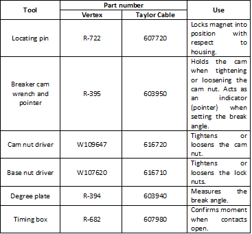
A quick post on some magneto tools. Most of the work on Vertex maggies can be done with simple hand tools. However, there are a few special tools that make life easier. Taylor Vertex sell most of the tools (http://www.taylorvertex.com), which I will discuss below.
The locating pin is a piece of bent wire that is 0.080” diameter.
It is used to lock the rotating assembly (magnet) to the housing during various tasks in the magneto overhaul process. The analogy for a distributor would be turning the dizzy until the rotor points to #1 cylinder in the dizzy cap, then locking the dizzy so it can’t turn. The locating pin currently sells for ~$US20. With care, a 1/16 or 5/32 drill bit will do the job.
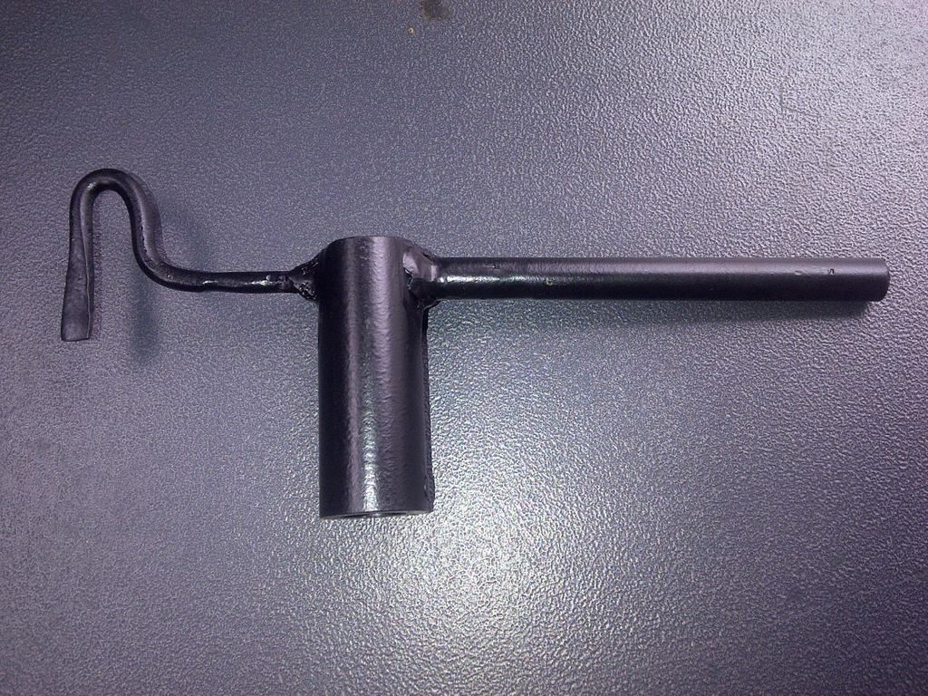
The breaker cam wrench and pointer is a more useful tool. It holds the breaker cam (without marking the cam faces) whilst the cam nut is done up securely (or loosened). It also acts as a pointer when setting the break angle.
When reassembling the magneto, the break angle must be correctly set. It determines when the magneto “fires” relative to the magnet position. The analogy would be setting the timing on an engine. Setting the break angle incorrectly means that the maggie will fire when the magnets and windings are not at their optimal alignment, leading to loss of power. The breaker cam wrench and pointer tool currently sells for ~$US55-$110.
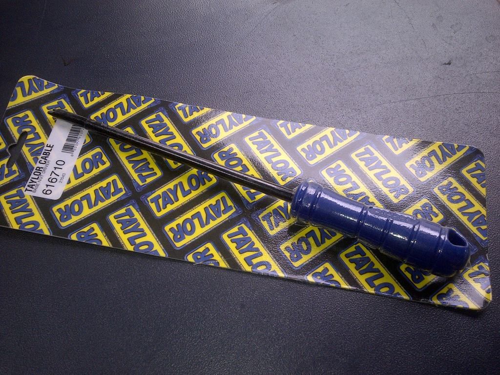
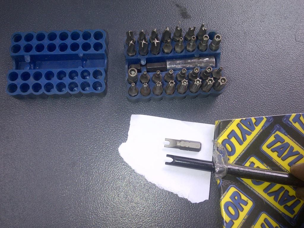
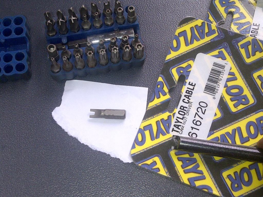
The cam nut driver and base nut driver tools are ones that I have my doubts about. The base nut driver is shown below.
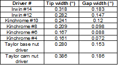
The cam nut and base nuts are a funky head, similar to the notched, H-type, snake eyes, pig nose, or spanner patterns. You can get at these nuts by grinding a slot into the tip of a large flat bladed screwdriver. As an alternative, you may be thinking of the Kinchrome Security Bit Sets that Bunnings sell. These have four bits (#4, #6, #8 & #10), though are a little small – see table below.
The photos below shows the base nut driver and then the cam nut driver alongside the #10 bit from Kinchrome set.
A better alternative is to buy the individual Irwin bits from eBay in #12 (part number 92571S) and #14 (92573S) sizes. The Irwin bits are worth ~$US6. The Taylor Vertex tools are worth ~$US70 each.
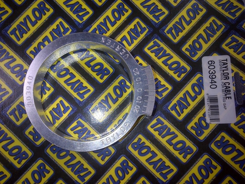
The degree plate is used (together with the breaker cam wrench and pointer tool) to measure the break angle. There is nothing fancy about the ring – it only measures angle about the centre shaft, just like a protractor.
With a little care, the degree plate could be made up from some stiff cardboard or light MDF and the markings made by using your kid's school pencil case protractor. The degree plate is worth ~$US65.
We have previously discussed the merits and cons of timing boxes (or “buzz boxes”). Whilst handy, they can be replaced by a simple multimeter (albeit you will need to disconnect some contacts whilst using one in lieu of a buzz box). Note that Taylor manufacture a buzz box for ~$US150. There are a number of other buzz box manufacturers (for example Joe Hunt Magnetos).
There are two tools that Scintilla originaly used for magneto overhauls that Taylor no longer produce. The first is a centrifugal weight locating tool (Vertex part number W109648), which is used to locate the centrifugal weights in the resting position during reassembly. The second is a ring (Vertex part number W79042) which is used when checking the sloppiness of the centrifugal advance weights. I have not been able to locate either of these tools, and have yet to see whether or not they are critical during an overhaul – more info once I get some maggies apart.
Cheers,
Harv
327 Chev EK wagon, original EK ute for Number 1 Daughter, an FB sedan meth monster project and a BB/MD grey motored FED.
Re: Harv's grey motor magneto thread
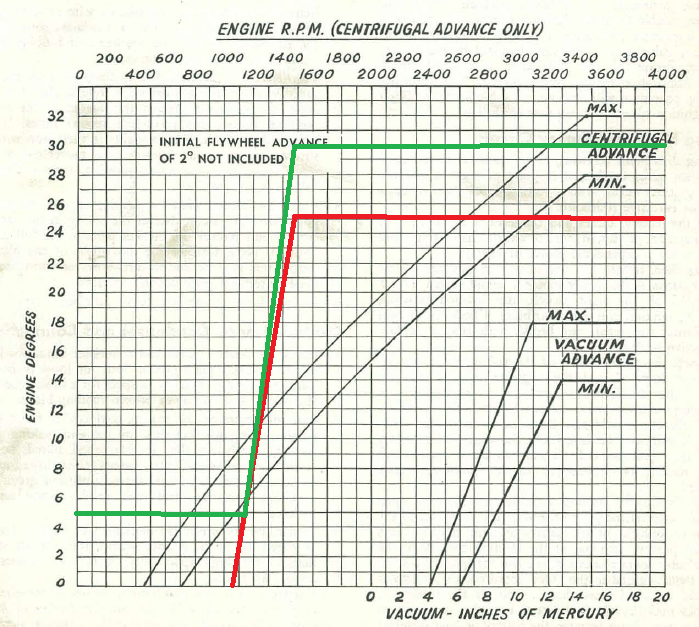
My apologies – I have made an error in the post above regarding the advance on the Vertex. I remembered that the speed shown on the Vertex nameplate refers to the magneto, and has to be doubled to get it back to normal crankshaft (engine) speed. I forgot that the advance angle also relates to the magneto, and also has to be doubled to get it back to normal crankshaft (engine) angle.
So, from the nameplate, we can see that the mechanical advance will start (0º) at 1060rpm, and wind up to 25º of advance at 1480rpm. Still not too optimal for a grey. The graph below shows what the Maggie will do (in red), and the effect of adding 5º of flywheel advance (in green).
Cheers,
Harv
So, from the nameplate, we can see that the mechanical advance will start (0º) at 1060rpm, and wind up to 25º of advance at 1480rpm. Still not too optimal for a grey. The graph below shows what the Maggie will do (in red), and the effect of adding 5º of flywheel advance (in green).
Cheers,
Harv
327 Chev EK wagon, original EK ute for Number 1 Daughter, an FB sedan meth monster project and a BB/MD grey motored FED.
Re: Harv's grey motor magneto thread
For interest, another twin-point grey motor dizzy is currently for sale on eBay:
https://www.ebay.com.au/itm/Holden-Grey ... :rk:3:pf:0
Its a Mallory ZB 180AX, with dwell of 39º. If this is 39º total dwell (very likely), then the only performance gain (over the factory 35-41º dwell) will be in reduced points float at high revs. If this is 39º dwell per point, then the total dwell (~48º) will give better zap over the factory dizzy. See the earlier posts on this thread for a discussion of twin-point dizzies.
Cheers,
Harv
327 Chev EK wagon, original EK ute for Number 1 Daughter, an FB sedan meth monster project and a BB/MD grey motored FED.
Re: Harv's grey motor magneto thread
I haven't seen this thread before, Harv. I've quickly scanned through the pages and, as usual, what a resource!
Thanks and cheers,
John
Thanks and cheers,
John
Re: Harv's grey motor magneto thread
Harv is there a definitive install guide anywhere for fitting a Scintilla to 138 grey?
Ive got the one Scotty Woodbridge had and looking to install - it's been set up for a 132 FJ grey with an extended shaft which should clear the side plate etc easy enough.
cheers
rob
Ive got the one Scotty Woodbridge had and looking to install - it's been set up for a 132 FJ grey with an extended shaft which should clear the side plate etc easy enough.
cheers
rob
You will find me lost somewhere!
Re: Harv's grey motor magneto thread
Assuming you have bought a magneto of “reasonable but unknown shape”, some rough notes below on getting it running.
a) Check that the rotation arrow on the cap is the same as the rotation of a grey motor dizzy (clockwise looking down onto the cap). You would not have been the first person to buy a magneto with the wrong orientation. It can be altered (by resetting break angle), but is not normally a DIY task.
b) Check to see if the dizzy still has mechanical advance (breaker plate can be gently rotated) or has been locked (breaker plate cannot be rotated independently of drive gear). The mech advance units are often (very) unreliable, so many were locked.
c) To lock the rotor on #1, take the spring clip that locks the cap screws from turning out and insert the open end into the small hole that is located on the bottom base. the hole is just big enough for the pin to slide into. Gently turn the drive shaft until you feel the pin drop into a receiving hole inside the mag. Once in the mag should not turn.
d) Take off the cap, being careful of the centre electrode cable.
e) Check points gap is somewhere between loose 0.015” to tight 0.016” clearance with a feeler gauge.
f) Put a dab of Vaseline on the breaker cam.
g) Take a look at where the rotor is pointing to. This is #1 cylinder, regardless of what is labelled on the cap stickers. Trace the terminal under the cap back to the lead outside the cap (carefull… the cap has funny channels inside it that means the leads can pop out in unusual locations). Put a piece of masking tape on that lead, labelled as #1.
h) Work your way around the INSIDE of the cap, starting at #1 terminal and see where spark will go next. Trace the terminal under the cap back to the lead outside the cap, and label that with tape as #2. Repeat for #3, #4, #5 and #6.
i) The cap of Vertex magnetos have wire position numbers (1, 2, 3, 4, 5, 6) labelled with white stickers. From the factory, the numbers indicate the sequence of firing of the magneto i.e. spark will flow from the wire labelled as #1 first, then #2, then #3 etc. This means that the stickers on your cap should be labelled the same as the bits of tape on your plug leads. This magneto firing order should not be interpreted as the firing order of the engine (for our grey motor 1, 5, 3, 6, 2, 4). Sometimes people replace the stickers with the 1, 5, 3, 6, 2, 4 order. Check your stickers, and note it down somewhere.
j) If your cap is labelled as per factory, you then need to work out what magneto wire to connect to which spark plug using the below:
Plug lead with #1 on piece of tape is connected to #1 cylinder.
Plug lead with #2 on piece of tape is connected to #5 cylinder.
Plug lead with #3 on piece of tape is connected to #3 cylinder.
Plug lead with #4 on piece of tape is connected to #6 cylinder.
Plug lead with #5 on piece of tape is connected to #2 cylinder.
Plug lead with #6 on piece of tape is connected to #4 cylinder.
If the cap was labelled with the 1, 5, 3, 6, 2, 4 order, then
Plug lead with #1 on piece of tape is connected to #1 cylinder.
Plug lead with #2 on piece of tape is connected to #2 cylinder.
Plug lead with #3 on piece of tape is connected to #3 cylinder.
Plug lead with #4 on piece of tape is connected to #4 cylinder.
Plug lead with #5 on piece of tape is connected to #5 cylinder.
Plug lead with #6 on piece of tape is connected to #6 cylinder.
k) If someone has butchered the leads, they may not be the correct length. The leads are held on to the cap with pointy brass screws. You can swap the leads around to get the correct length on the correct cylinder. If you do, double check the plug order again.
l) Turn your engine around until the dizzy is pointing to #1 cylinder. Remove the dizzy, and drop in the maggie (still locked at #1). Remove the locking pin before turning the engine!
m) DO NOT TURN OVER THE ENGINE UNTIL YOU HAVE FITTED AN EARTH SWITCH TO THE P-TERMINAL OF THE MAGNETO. If the engine is turned over, it is likely to fire. The ignition switch will not stop the engine.
n) The wiring required will depend on how fancy you want to get. A simple hi-amp earth switch on the dash will do it. You can also get fancy and use a relay so that the original key switch works. In any case the coil is redundant and can be removed. The pink coil power feed can be used to power the relay if you choose to go that way. DO NOT EVER, EVER CONNECT +12V TO A MAGNETO (unless you particularly like the smell of magic smoke)! The only connection made to the maggie is the earth kill switch.
o) The timing of the maggie may be interesting. If the maggie has been converted to fixed advance, then the timing is going to need to be set (maggie rotated) to get the total advance right. Initial advance will be crap (waaaay to advanced) and the car may be hard to start. One trick is to leave the maggie off (earthed), spin the starter up with the key, then un-earth the maggie.
p) Never rely totally on your timing light as your sole source for timing your motor. Timing lights are typically D.C. and magnetos generate A.C. They also emit E.M.I. (Electro Magnetic Interference). In general, timing lights with mags are one degree late for every 1000 RPM of engine speed. For best results, use a timing buzzer. Check both idle advance and advance at speed. There is a fair bet that the advance curve is crap… many dizzies were converted to grey motor use with little, if any, change to the advance weights. The curves are often for slow, plodding industrial motors rather than road vehicles.
Cheers,
Harv
327 Chev EK wagon, original EK ute for Number 1 Daughter, an FB sedan meth monster project and a BB/MD grey motored FED.
Re: Harv's grey motor magneto thread
Champion Harv - I might try and enlist Scotty to help with install so I dont cock it up.
This Mag was set up and tested by Don Zig in the states
10Deg static timing
22 deg in mag plates and base
32 deg at 3500
was tested to 7000 rpm but I am 100 percent sure I wont be going into that territory.
I was reading your info in this thread re the radio interference - can that be overcome? I'm taking out the AWA AM unit and fitting a new fangled AM/FM bluetooth unit - can they be isolated somehow to reduce noise?
You will find me lost somewhere!
Re: Harv's grey motor magneto thread
That's a nice curve.
For the interference, you can run shielded wires (bit less zap than the copper-core leads though). There are also shielded caps available, but rare.
Turn the wireless off, wind the windows down and listen to the grey .
Cheers,
Harv
For the interference, you can run shielded wires (bit less zap than the copper-core leads though). There are also shielded caps available, but rare.
Turn the wireless off, wind the windows down and listen to the grey .
Cheers,
Harv
327 Chev EK wagon, original EK ute for Number 1 Daughter, an FB sedan meth monster project and a BB/MD grey motored FED.
Re: Harv's grey motor magneto thread
LOL - will be a fair bit going on - 2 inch pipes - Wray Super charger - Maggie - Genpower Alternator - might need the radio turned up - hahaha
Harv wrote: Thu Nov 21, 2019 10:05 am That's a nice curve.
For the interference, you can run shielded wires (bit less zap than the copper-core leads though). There are also shielded caps available, but rare.
Turn the wireless off, wind the windows down and listen to the grey .
Cheers,
Harv
You will find me lost somewhere!
Re: Harv's grey motor magneto thread
Some pics of mine
Sent from my iPhone using Tapatalk Pro
You will find me lost somewhere!
Re: Harv's grey motor magneto thread
Harv,
You write,
"p) Never rely totally on your timing light as your sole source for timing your motor. Timing lights are typically D.C. and magnetos generate A.C. They also emit E.M.I. (Electro Magnetic Interference). In general, timing lights with mags are one degree late for every 1000 RPM of engine speed."
I didn't think there was that much difference between a coil ignition and a magneto ignition as far as the high-tension waveform is concerned (apart from a much higher spark energy with a magneto). An ignition coil produces mainly high-frequency AC from the secondary also.
A timing light triggers on the sharp rise in secondary voltage when the points open, rather than at a predetermined voltage level. Let me think about the timing delay problem. 1000 rpm is 360000 degrees per minute, 6000 degrees per second. So if a timing light delays a degree per 1000 rpm, that's equivalent to a trigger delay of 1/6000 seconds, i.e. 166 microseconds. I don't know. I'd have expected a timing light to fire within a couple of microseconds.
Maybe a magneto generates more radio interference than a coil ignition because of the higher spark energy. But I'd also have thought that the same interference suppression techniques as with coil ignition would be successful with a magneto. Maybe resistive HT cables dissipate too much spark energy. Do you mean resistive cables or shielded cables? Shielded cables are like high-voltage coax cables, and require a ground connection for the outer conductor.
Anyway, enough musing.
Rob
Re: Harv's grey motor magneto thread
To my understanding, the main issue is RF noise rather than triggering. I could be wrong though.
The Vertex manual (in italics below) gives some good guidance on the shielding:
Thre are two types of suppression:
1. Distant interference suppression
2. Close interference suppression
1. Distant interference suppression: Every VERTEX can be suppressed for distant interference without big alterations, it being only necessary to replace the distributor rotor by one with built in 5000 ohm resistance (Part No. 1643}. In addition to this resistance, however, resistance should be fitted next to the spark plugs by means of either special resistance-type plugs or plug connectors with built-in resistance. When selecting these resistances. note that the total resistance per ignition circuit should not exceed 10,000 ohms.
2. Close interference suppression: If the suppression has to be more thorough, the VERTEX must be screened. This is the case with vehicles and aircraft fitted with highly sensitive radio transmitters and receivers. This screening, comprising a special metal hood and screened -cables, can also be applied to any VERTEX without great alterations.
I was suggested option 1 (modern resistive cables instead of the original copper-core ones, perhaps resistive plugs) as the components for option 2 (cap hood and earthed, shielded cable shrouds like the HV coax) are pretty rare. There are some photos of option 2 earlier in this thread.
Cheers,
Harv
327 Chev EK wagon, original EK ute for Number 1 Daughter, an FB sedan meth monster project and a BB/MD grey motored FED.