My new Fb

Post photos of your pride and joy, or updates on your rebuild!

Moderators: reidy, Blacky

User avatar
thebrotherj
Posts: 682
Joined: Wed Aug 21, 2013 4:09 pm
State: NSW
Location: Sydney

Re: My new Fb

Post by thebrotherj »

Devilrod wrote:I m blown away by the rubber boot you made!! That's freakin' awesome. Great work.
x2 from me! Epic effort Image


Sent from my iPhone using Tapatalk
User avatar
59wagon
Posts: 645
Joined: Sun Jul 27, 2014 11:40 am
State: WA
Location: Shoalwater, WA

Re: My new Fb

Post by 59wagon »

Thanks you blokes, I’m happy you got something from it Image

Next was to get the front apron off

Image

Image

Image

Image

Some nice reveals here .....

Image

Image

..... and some Mig wire sprouting from a previous repair Image

Image

I’ll need to make this top section later on as I don’t think they’re available as a repro. I have a new bottom section.

I sandblasted half of the apron underneath then decided to do some repairs, first on some dents on the rh side

Image

Image

In the wood vice to flatten it a bit

Image

Then I used a plastic headed hammer and a piece of wood as a dolly to minimise stretching the metal - sorry forgot to take pics of that.
Now a metal hammer to finish off on the steel table

Image

Image

Image

Both bolt clearance holes near these dents were torn and buckled so, using a copper backing bar, I migged up the holes. Here’s a top and bottom shot of the weld - using the copper backer helps reduce grinding as well as absorbing some heat.

Image

Image

Image

and some new 3/8” holes. I started with a 1/8” drill bit and worked up to the 3/8” by using every second bit.

Image

I then straightened out the corresponding section on the car

Image

and checked the fit, only to find I was about half a hole out Image

Image

I was pretty confident I’d drilled the holes back in the right spot and some measuring confirmed this. A bit of investigating found that the rhs cross member was a bit mangled and the fender was sitting about 1/4” lower than the cross member. Here’s some comparison pic’s of left vs right

Image

Image

Image

Image

After bashing the lhs cross member tab back to where it should be and panel beating the return flanges on the apron and fender

Image

I then had to loosen the front fender bolts to raise the fender to line up with the cross member

Image

All good now

Image

The fenders will be coming off anyway for repairs but at least now I know how to make the fender and apron line up.

Cheers,

John


Sent from my iPhone using Tapatalk
User avatar
Errol62
Posts: 10484
Joined: Sat Dec 06, 2014 2:44 pm
State: SA
Location: Adelaide

Re: My new Fb

Post by Errol62 »

Good post John. Just getting things apart without snapping off half the bolt heads is an achievement in itself. Did you blast the panel out in the yard? I can’t see that you could do it in a cabinet. I’ve ordered a wet blasting fitting for the gurney to try out.


Sent from my iPhone using Tapatalk
getting my FB ute on the road
EK van on rotisserie
User avatar
59wagon
Posts: 645
Joined: Sun Jul 27, 2014 11:40 am
State: WA
Location: Shoalwater, WA

Re: My new Fb

Post by 59wagon »

Thanks Clay. I think I snapped a couple of bolts on the way.
I did the blasting in the cabinet. With the vacuum setup, I can leave the door open and not get dust coming out, just a bit of sand is blown out. I put a loose sheet over the door so the sand just drops to the floor for a sweep up.
I’d be interested to see how your gurney works. I’ve used a wet blaster before at work and you just need to make sure you dry and prime your parts straight away otherwise they start rusting almost immediately.

Cheers,

John


Sent from my iPhone using Tapatalk
User avatar
59wagon
Posts: 645
Joined: Sun Jul 27, 2014 11:40 am
State: WA
Location: Shoalwater, WA

My new Fb

Post by 59wagon »

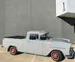
Next job is to make the top half of the front cross member to replace this

Image

With a combination of a cheap spot drill that I broke a few teeth off,

Image

a hammer and sharpened wood chisel, made for metal Image,

Image

a cut off wheel,

Image

and a few choice words,

Image

I got it off and give it a clean so I could get some measurements

Image

Image

Found a few mud boondies sitting in the bottom section, amongst other stuff

Image

This section was going to be a bit more complicated than I initially thought. There were 90 degree bends turning into about 60 degree bends around a radiused corner and, together with bends being close together, pretty much made my little 600mm folder not much use here.
I pondered for ages on how to do this

Image

I thought hammer forming over a wooden form probably wouldn’t work well due to the radiuses and shrinking required, and the fact that the metal is about 1.6mm thick - I didn’t have any 1.6mm in cold rolled, so I settled for some zincalume that I have, which is harder to bend again.
I decided to make some steel moulds and use the hydraulic press. I’d never done this before and thought I’d make the piece in three sections and then weld together.
Here’s the moulds with alignment holes

Image

Image

and a test piece in 1.2mm cold rolled (I didn’t have enough 1.6mm to waste on practicing) next to the original and the zincalume piece I’d use

Image

The moulds took a while to make due to the radiuses and angles

Image

Image

Also, the cross member tapered down from 1/2” at the front to 3/8” at the back. When I cut the steel from some 3/8” C channel, I cut “around the corner”, if that makes sense, so I had 1/2” at one end and 3/8” at the other. I could then weld a plate to these and have the required angles. Pic’s might explain better

Image

Image

Image

Image

I then drilled locating holes in the two moulds and zinc sheet, including a 11/32” where one one of the 5/16” fixing bolts go, and two 9.5mm holes for extra locating pins (3/8”bolts).

Image

Off to the press

Image

Almost there

Image

Done

Image

It got up to about 7 tonnes on the gauge, the 1.2mm test piece was about 5 tonnes

Image

You can see some puckering in the sheet where the metal had to shrink at the corner, which is a tad less than 90 degrees

Image

Image

Now I had to bash, or hammer form, the return after trimming closer to actual size. You can also see the curve in the mould that I used as a form

Image

Image

Had to be careful at this awkward bit as a bit of shrinking had to happen. I used the ball pein end mainly here.

Image

Trimmed again and the end tab cut out

Image

That’s as far as I’ve got to now. For the other bits, I might experiment with wood moulds.

Cheers,

John


Sent from my iPhone using Tapatalk
User avatar
59wagon
Posts: 645
Joined: Sun Jul 27, 2014 11:40 am
State: WA
Location: Shoalwater, WA

My new Fb

Post by 59wagon »

I wanted to try an LED for the interior light and bought two for $5.99 on eBay, free postage. Same price or cheaper than a filament globe.

The old and the new

ImageImage

A bit hard to show in photos, but the LEDs seem to give a better light, and definitely whiter than the filament.

First is LED, second is filament

ImageImage

and again

ImageImage

and again with the dome cover removed - I reckon I could do with a newer, lesser opaque cover .....

ImageImage


Sent from my iPhone using Tapatalk
User avatar
Errol62
Posts: 10484
Joined: Sat Dec 06, 2014 2:44 pm
State: SA
Location: Adelaide

Re: My new Fb

Post by Errol62 »

Incredibly resourceful as ever John.


Sent from my iPad using Tapatalk
getting my FB ute on the road
EK van on rotisserie
User avatar
Harv
Posts: 5315
Joined: Mon Oct 08, 2007 2:00 pm
State: NSW
Location: Sydney, Australia

Re: My new Fb

Post by Harv »

Crikey John, you're looking a little thin in the photos. If my nanna was still with us, I'd send you round to her place for a decent feed :lol: .

The LED bulbs are a great idea. Brakes/indicators/taillights/parkers are easy too, though may need to change the flasher can to an LED type. There is a mob making fancy parker bulbs that are white for the parker, and orange for the indicator. Tres cool 8) . The only drama I have had is some of the replacement dash light bulbs on eBay are wired the wrong way. Being a diode, they won't work if the positive and negative terminals are swapped.

Cheers,
Harv
327 Chev EK wagon, original EK ute for Number 1 Daughter, an FB sedan meth monster project and a BB/MD grey motored FED.
User avatar
59wagon
Posts: 645
Joined: Sun Jul 27, 2014 11:40 am
State: WA
Location: Shoalwater, WA

Re: My new Fb

Post by 59wagon »

Harv wrote: Sat Sep 01, 2018 6:16 am The LED bulbs are a great idea. Brakes/indicators/taillights/parkers are easy too, though may need to change the flasher can to an LED type. There is a mob making fancy parker bulbs that are white for the parker, and orange for the indicator. Tres cool 8) . The only drama I have had is some of the replacement dash light bulbs on eBay are wired the wrong way. Being a diode, they won't work if the positive and negative terminals are swapped.
Good to know, thanks Harv. Are the dash lights the different colour ones I’ve seen on ebay?
User avatar
Harv
Posts: 5315
Joined: Mon Oct 08, 2007 2:00 pm
State: NSW
Location: Sydney, Australia

Re: My new Fb

Post by Harv »

Yep.

I bought two batches on eBay from the same seller (one coloured, one clear). The clear ones were OK (positive to the end terminal, negative to the bulb body), but the coloured ones were wired the opposite way. Suspect they may have been made for a Toyota, as some of the Toyota wiring is done that way.

As an aside, I never want to play with Tarago wiring ever again. It once took me a full day to put headlight relays into one due to the funky switching. It used to fire up both the high beam filament and low beam filament when on "High". After getting the relays in, I fitted it with 130/90W H4 bulbs. With both filaments lit, it lit up the highway like noon... and drew enough amps to melt the common earth pin out of the H4 bulbs :shock: . Kinda glad I fitted relays.

Cheers,
Harv
327 Chev EK wagon, original EK ute for Number 1 Daughter, an FB sedan meth monster project and a BB/MD grey motored FED.
User avatar
59wagon
Posts: 645
Joined: Sun Jul 27, 2014 11:40 am
State: WA
Location: Shoalwater, WA

My new Fb

Post by 59wagon »

I finally got to completing the upper front cross member. I made another set of moulds as a mirror image of the previous set for the other end piece, then set about making a set of moulds for the centre piece. These took ages as the part has all sorts of awkward angles and indentations but we finally got there. The pic’s below show the centre piece with the two end pieces already welded on.

Image

Image

Image

Forming the piece in the press took about 20t of force and I had to move the piece along to do it in stages as it would flex.
After welding the three bits together, hammer forming the returns and making some adjustments, I carefully marked out for the various holes to be drilled.
Next was to make six new 1/4” unf “nut plates” as the old ones weren’t in very good nick.

Image

The originals were attached with four very small spot welds and I initially thought I would plug weld with similar sized holes (11/64”) but, after drilling the 24 holes, I did a test weld and found it failed miserably.
Dr Google says plug welds usually use between 1/4” and 5/16” holes for plug welds depending on sheet thickness. So I experimented using 6,7 and 8mm holes.

Image

Here’s the backside showing penetration and you can see how it gets better with a bigger sized hole

Image

I then used a chisel to separate the pieces. The 6mm came off without much force and the 7mm needed a touch more. You can see there isn’t much welding going on here

Image

The 8mm hole was beaut. I couldn’t separate the two pieces and the metal just deformed as I tried.

Image

As 8mm holes weren’t going to fit on these plates, I decided I’d fillet weld instead and fill the holes I’d already drilled. First I attached the apron with bolts to ensure everything lined up, and then tacked the plates before removing the apron and completing the welds.

Image

Image

Image

Now to make and attach the 2 brake line clips.
Here’s the original.

Image

Just a few minutes with hammer, vice, clamp and a couple of bits of 3/16” rod.

Image

Image

Image

Image

Image

Here’s the completed part with the Rare Spares lower section that it’ll be plug welded to later on

Image

I’ll paint the inside of this part with zinc paint before welding.

Cheers,

John


Sent from my iPhone using Tapatalk
User avatar
FJWALLY
Posts: 1833
Joined: Wed Nov 11, 2015 4:54 pm
State: VIC
Location: Forest Hill

Re: My new Fb

Post by FJWALLY »

Some very patient and Awesome Ingenuity going on there John - thanks for sharing - very interesting reading.
You will find me lost somewhere!
User avatar
Errol62
Posts: 10484
Joined: Sat Dec 06, 2014 2:44 pm
State: SA
Location: Adelaide

Re: My new Fb

Post by Errol62 »

Bluddy awesome John.


Sent from my iPhone using Tapatalk
getting my FB ute on the road
EK van on rotisserie
Blacky
Posts: 12937
Joined: Tue Jul 20, 2004 8:58 am
State: WA
Location: up in the Perth hills

Re: My new Fb

Post by Blacky »

nice work JB , now that you have it sorted can you knock me up a couple ????? :ebiggrin: :ebiggrin:
You coming on Sunday ????
I started with nothing and still have most of it left.


Foundation member #61 of FB/EK Holden club of W.A.
User avatar
FireKraka
Posts: 2486
Joined: Fri Jan 24, 2014 11:12 am
State: WA
Location: Serpentine, WA

Re: My new Fb

Post by FireKraka »

I second what Blacky said I'm in for one; you better get to work John :ebiggrin:

Neil
Member of WA FB/EK Car Club
Frankenstein EK V6 Ute
The Reverend FB Station Wagon Project
1950's Commer Light Truck (2.5 Ton)
Post Reply